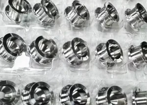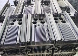
Titanium alloys offer low density, high specific strength, excellent high-temperature mechanical properties, corrosion resistance, and good biocompatibility. These properties support applications in aerospace, petrochemicals, marine engineering, automotive manufacturing, and biomedicine.
In recent years, aerospace vehicles have faced increasingly demanding service requirements.
As a result, titanium alloy usage has increased significantly in critical components and aircraft structures. China has enormous demand for processed titanium products, particularly for large commercial aircraft manufacturing.
Global titanium product output reached approximately 260,000 tons in 2024. Aerospace, medical, and emerging applications accounted for about 58% of global demand.
Titanium consumption also grew rapidly in China’s aerospace, power, and shipbuilding industries during the same year.
These sectors represented approximately 30.2% of China’s annual titanium consumption. The 3C sector, including computers, communications, and consumer electronics, also grew rapidly. Annual titanium consumption in the 3C sector exceeded 11,000 tons.
However, low thermal conductivity and high chemical activity make titanium alloys difficult to machine. Conventional cutting methods often struggle to maintain dimensional accuracy and surface quality.
These limitations increase production costs and restrict wider applications of advanced titanium alloys. Major machining challenges include excessive cutting temperatures caused by low thermal conductivity.
A low deformation coefficient also intensifies rake-face wear. High cutting forces occur over a small rake-face contact area.
A low elastic modulus increases flank wear, while high chemical activity further complicates machining. Researchers worldwide have therefore explored advanced cutting technologies to overcome these limitations.
However, several technical challenges remain unresolved. Recent research covers advanced cutting technologies, machining research methods, chip characteristics, cutting processes, and cutting tools.
Understanding their advantages and limitations can support further development of titanium alloy machining.
Advanced Cutting Technologies for Titanium Alloys
Rapid developments in aerospace and deep-sea engineering have increased the complexity and size of critical components. These changes demand better surface integrity, machining accuracy, and production efficiency.
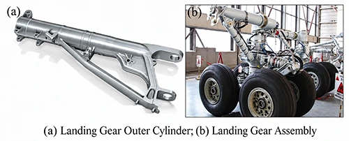
A large aircraft landing gear may span 2–6 meters and feature a high length-to-diameter ratio. It may also contain rotational surfaces and asymmetric spatial structures.
More than 160 precision operations may be required to complete such a component.
These demanding applications expose important limitations of conventional cutting technologies. Low efficiency, high manufacturing costs, and poor repeatability between operations have become increasingly significant.
Conventional processes therefore struggle to satisfy modern titanium component manufacturing requirements. Researchers have developed several advanced technologies to address these problems.
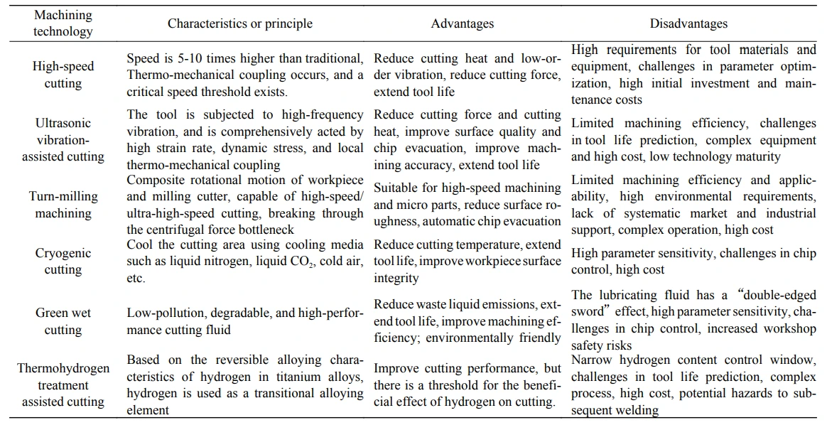
They include high-speed cutting, ultrasonic vibration-assisted cutting, turn-milling, cryogenic cutting, green wet cutting, and thermohydrogen treatment-assisted cutting.
High-speed cutting provides an efficient and economical method for producing high-quality precision components. Its cutting speed is usually five to ten times higher than conventional cutting.
For titanium alloys, cutting speeds above 150 m/min can generally be considered high-speed cutting. The process involves severe deformation, high strain rates, high temperatures, and complex thermo-mechanical coupling.
These conditions fundamentally change the cutting mechanism. Studies show that high-speed cutting can reduce cutting heat and low-order cutting vibration. Cutting force may decrease by approximately 30%, while tool life may increase by 70%.
These improvements make high-speed cutting attractive for titanium alloy machining. Ultrasonic vibration-assisted cutting is another emerging machining technology.
It can reduce cutting force and heat while improving workpiece surface quality.
The process can also refine the surface microstructure and improve machining quality. High-frequency vibration produces an intermittent cutting motion during machining.
Therefore, the tool periodically contacts and separates from the workpiece. Compared with conventional cutting, this process involves high strain rates and dynamic stresses.
Local thermo-mechanical coupling can also significantly change the subsurface and matrix microstructures.
Typical methods include one-dimensional and two-dimensional ultrasonic vibration-assisted cutting. Ultrasonic elliptical vibration-assisted cutting is a special form of two-dimensional ultrasonic vibration cutting.
Its elliptical trajectory develops within one plane by controlling the phase difference. Both vibration directions require precise synchronization to maintain a stable elliptical trajectory.
This micron-scale ultrasonic elliptical vibration can reduce cutting forces and tool wear. It also improves heat dissipation and promotes chip breaking or evacuation.
These effects can further improve workpiece surface quality. Turn-milling uses combined rotational movements between the workpiece and milling cutter.
The process integrates effectively with CNC machining systems. Different relative positions between the cutter and workpiece create orthogonal, tangential, and axial turn-milling methods. Orthogonal turn-milling combines slow workpiece rotation with high-speed cutter rotation.
This configuration enables high-speed or ultra-high-speed cutting. It also avoids limitations caused by excessive chuck and workpiece rotational speeds during high-speed turning. Orthogonal turn-milling can promote automatic chip evacuation.
Consequently, it significantly reduces chip entanglement. Cryogenic cutting cools the cutting zone using liquid nitrogen, liquid carbon dioxide, or cold air.
Its main principle involves lowering cutting temperature and reducing material plasticity and toughness.
Cryogenic cutting can use either internal or external cooling methods. Researchers have also combined cryogenic cutting with minimum quantity lubrication. This approach sprays a low-temperature aerosol containing coolant and a small amount of cutting fluid into the cutting zone.
It provides strong cooling and lubrication simultaneously. The method therefore shows considerable potential for engineering applications. Green wet cutting provides another environmentally focused machining approach.
It uses low-pollution, biodegradable, high-performance cutting fluids. These fluids can reduce waste discharge, extend tool life, and improve machining efficiency.
Thermohydrogen treatment-assisted cutting uses the reversible alloying behavior of hydrogen in titanium alloys. Hydrogen serves as a temporary alloying element to improve machinability.
The process generally includes hydrogenation, thermal treatment of hydrogen-containing material, and vacuum dehydrogenation.
Applications already include cast titanium alloys, titanium matrix composites, residual titanium processing, and mechanical property improvement.
Research Methods for Titanium Alloy Cutting
Metal cutting essentially involves complex elastic-plastic deformation under high temperatures, high loading rates, and repeated thermo-mechanical impacts.
Common research methods include conventional experiments, Hopkinson pressure-bar tests, constitutive modeling, and numerical simulation.
Advanced cutting technologies have exposed limitations in conventional experimental methods. Challenges include high-strain-rate testing, small-sample mechanical analysis, transient strain-rate simulation, and thermo-mechanical coupling studies.
High economic and time costs also restrict conventional experimental methods. Hopkinson techniques offer lower costs and simpler operation for studying material cutting behavior.
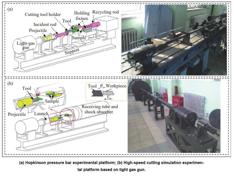
The split Hopkinson pressure bar forms the core experimental apparatus. Cutting tests at 5–30 m/s generally use a Hopkinson pressure-bar system. Tests at 30–250 m/s commonly use light-gas-gun experimental systems.
These methods enable researchers to investigate cutting behavior under high-speed loading conditions.
Researchers have also developed constitutive models using dynamic mechanical property data.
Examples include conventional and modified Johnson-Cook models, Zerilli-Armstrong models, and mechanical threshold stress models.
Other approaches include Khan-Huang, Bodner-Partom, and Campbell models. The Johnson-Cook model remains widely used because of its simple structure and convenient fitting process.
Researchers developed a Johnson-Cook model for TC21 alloy using Hopkinson pressure-bar experimental data.
The model was then applied to predict deformation during high-speed cutting. Titanium alloy machining environments have become increasingly specialized and complex. Researchers have therefore developed modified Johnson-Cook models for more accurate predictions.
One approach introduced a strain-softening term into the Johnson-Cook model. This modification produced a TANH, or hyperbolic tangent, model.
Comparisons showed that the conventional Johnson-Cook model predicted cutting parameters at approximately twice the experimental values.
The TANH model predicted chip strain states and chip morphology more accurately.
Numerical methods have also advanced significantly, including finite element, finite volume, finite difference, and boundary element methods. These technologies reduce the time, space, and economic costs of machining research.
Multiphysics simulations and dynamic visualization can reproduce microscopic phenomena such as chip formation and tool wear.
These capabilities support cutting-parameter optimization and improvements in machined surface integrity. Finite element methods were first applied to metal cutting research in 1974.
Researchers used these models to analyze temperature conditions within orthogonal cutting zones.
Growing engineering demand has increased the importance of numerical simulation in titanium alloy machining.
Three-dimensional finite element models can compare cutting tools with different coating materials. Researchers have examined uncoated, TiAlN-coated, and TiAlN+cBN-coated tools when machining Ti-6Al-4V.
The analyses considered cutting force, temperature, chip morphology, and tool wear. Other studies combined finite element methods with constitutive models and ductile failure mechanisms.
These approaches revealed cutting temperature and strain distributions in Ti-6Al-4V. The results demonstrated the importance of material failure and damage evolution in serrated-chip formation.
Numerical simulations have also evaluated newly designed WC/Co carbide tools containing micro-grooves.
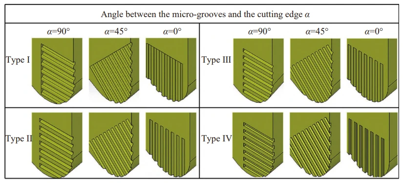
Micro-grooved tools can reduce cutting force, cutting temperature, and stress concentration around cutting edges. Finite element methods can also predict temperature distributions at tool-chip interfaces. However, efficient and accurate numerical predictions remain difficult.
Major limitations include model accuracy, machining complexity, long simulation times, and limited parameter-optimization methods.
Titanium Alloy Chip Characteristics
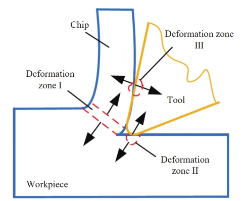
Interactions between the workpiece and cutting tool generate chips during metal cutting. Three important deformation zones exist among the workpiece, tool, and chip.
The first zone is the shear-slip deformation region and represents the main deformation zone. Material undergoes plastic deformation and shear slip there, producing chips.
Friction and compression between chips and the rake face intensify chip deformation and increase temperature.
The second zone lies along the frictional contact between chips and the tool rake face. Material near the rake face gradually becomes fibrous within this region.
Chip-flow velocity decreases, while chip curling promotes additional frictional heat. The third zone lies between the tool flank and the machined workpiece surface.
Cutting heat and force act directly on the workpiece surface there. Cutting heat mainly originates from three sources.
These include plastic deformation, friction between chips and the rake face, and flank friction against the machined surface.
Heat leaves these regions through conduction into the workpiece, chips, and cutting tool. Cooling media and cutting fluids can also remove heat.
Chip morphology strongly influences cutting force, temperature, efficiency, tool life, and workpiece quality.
Common chip forms include ribbon, serrated, C-shaped, granular, spiral, and pagoda-shaped chips. Serrated chips are particularly characteristic of titanium alloy machining. However, researchers still debate their exact formation mechanism.
Two major explanations are the adiabatic shear theory and periodic fracture theory. Adiabatic shear theory links serrated chips with localized plastic deformation.
High-strain-rate regions develop adiabatic shear bands because of strain concentration and thermal softening. This localized nonuniform plastic deformation eventually promotes serrated-chip formation.
Early research associated adiabatic shear bands with thermoplastic instability during metal deformation. Later Hopkinson pressure-bar experiments identified their initiation and full development in Ti-6Al-4V specimens.
Research on Ti-25V-15Cr found typical serrated chips and numerous shear bands inside beta grains. Increasing cutting speed raised the frequency of adiabatic shear bands.
Subgrains between these shear bands also became finer. Consequently, the serrated characteristics became more pronounced.
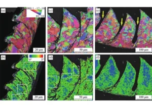
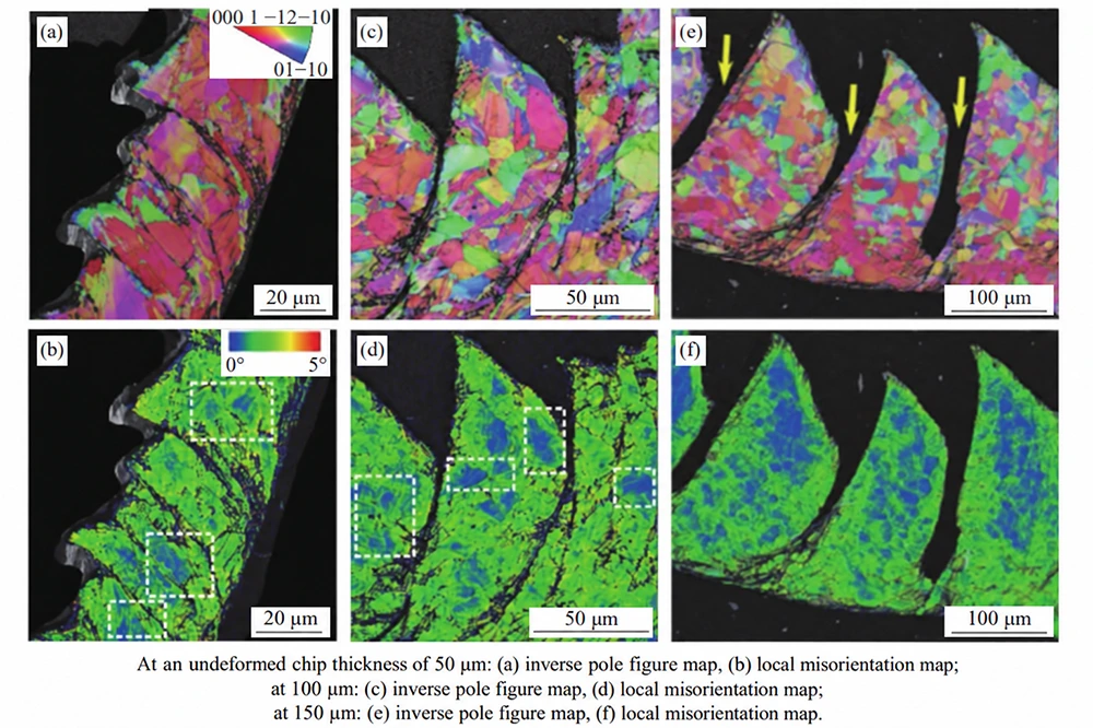
EBSD studies examined Ti-6Al-4V chips with different undeformed thicknesses. At 50 μm, cutting deformation remained relatively uniform. Primary alpha phases showed limited deformation under these conditions.
Serrated regions mainly appeared around phase interfaces or low-strength regions within alpha-plus-beta lamellar colonies.
At undeformed chip thicknesses of 100 or 150 μm, primary alpha phases could be cut. Regular serrated chips mainly developed through adiabatic shear bands or crack initiation.
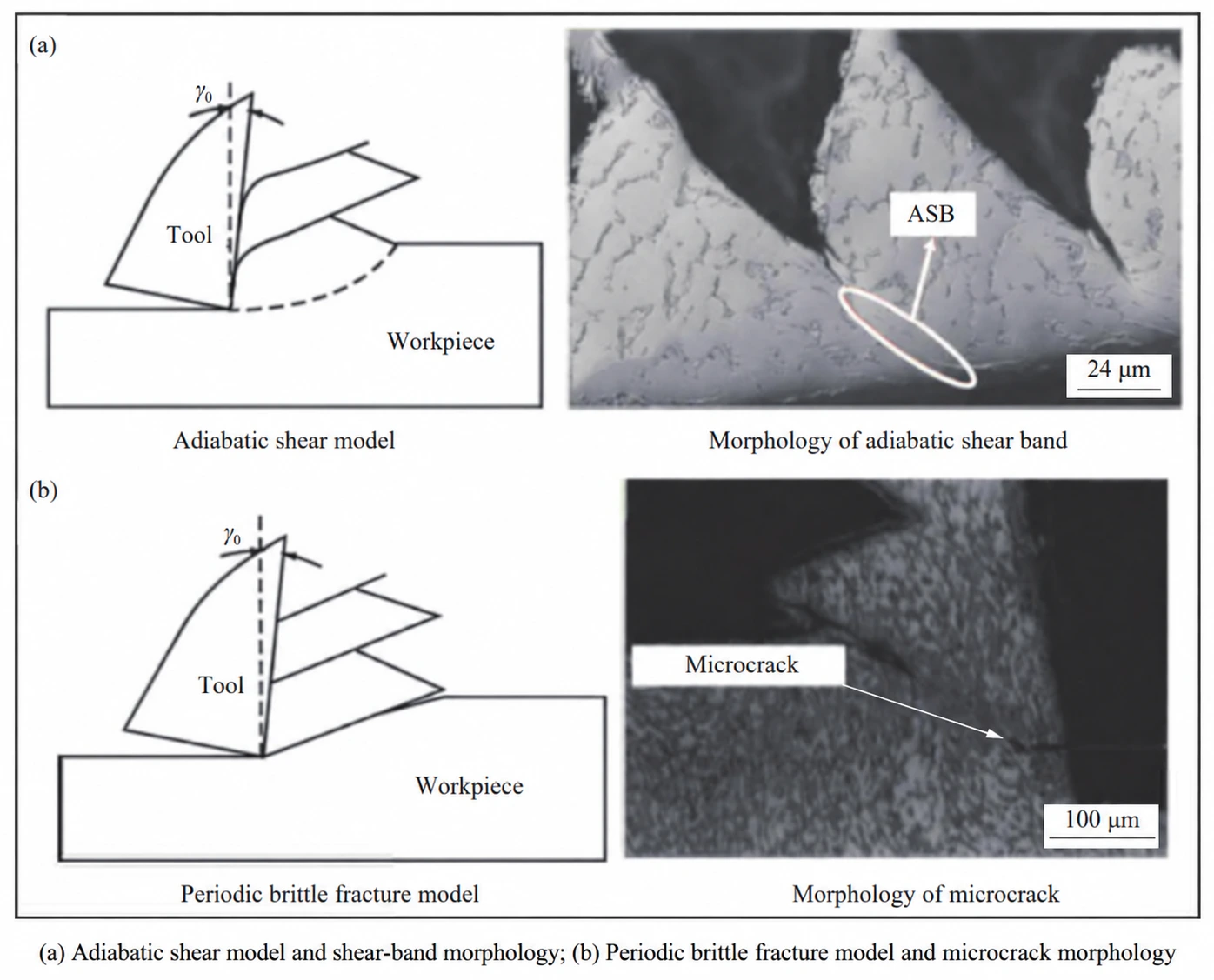
Periodic fracture theory provides another explanation for serrated chips. It attributes their formation to periodic fracture caused by crack-induced geometric instability.
Individual chip segments contain discontinuous microcrack regions and continuous coarse cracks across their width. These regions represent localized and overall brittle fracture behavior.
Research has linked serrated-chip formation to cyclic cracking. Some studies found that the tendency toward serration decreased as cutting speed increased.
Other experiments using air-gun systems examined Ti-6Al-4V chip roots. Their results associated serrated-chip formation primarily with surface crack propagation.
Researchers have also considered crystal structure and cutting conditions. Studies have compared pure titanium, alpha-plus-beta alloys, and beta titanium alloys.
These investigations attempt to connect serrated-chip characteristics with crystal structure. Current research generally gives greater attention to adiabatic shear theory when explaining serrated titanium chips.
Effects of Cutting Parameters on Titanium Alloy Cutting Behavior
Cutting force and cutting temperature are important physical quantities for evaluating metal machining behavior.
Cutting force represents material resistance against the cutting tool. The average temperature within the contact region between the tool rake face and the chip is generally defined as the cutting temperature.
Excessive force and temperature can adversely affect surface quality and tool life. Their combined effects may also create risks for component performance.
Cutting speed, cutting depth, and feed are therefore fundamental process parameters.
Interactions among these parameters strongly influence the dynamic evolution of cutting forces and temperatures.
Their effects should therefore be evaluated together rather than independently.
Cutting Speed
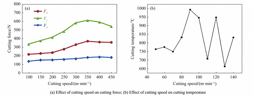
Finite element simulations evaluated Ti-6Al-4V cutting speeds between 150 and 450 m/min. Cutting force initially increased and then decreased as speed increased. This behavior indicates that cutting speed has a threshold effect on cutting force.
Experiments on TC18 alloy also evaluated milling speeds from 50 to 140 m/min. Cutting temperature increased with milling speed.
However, the rate of temperature increase depended strongly on the milling-speed range. Below 70 m/min, cutting temperature increased slowly.
Between 70 and 100 m/min, cutting energy consumption and total generated heat increased significantly.
Consequently, cutting temperature rose rapidly. Above 100 m/min, chips removed considerably more heat from the cutting zone. Less heat therefore entered the workpiece or tool.
Cutting temperatures fluctuated between approximately 650 and 1,000°C under these conditions. Studies of Ti-6Al-4V orthogonal milling found greater surface strain and plastic deformation depths at lower milling speeds.
Cutting speed can also influence residual stress. Residual compressive stress on the machined surface increased with cutting speed in one study. Increasing speed intensified surface plastic deformation and thermo-mechanical effects.
Phase transformations can also change phase proportions near the machined surface. The resulting lattice distortion contributes to residual stress.
Cutting Depth
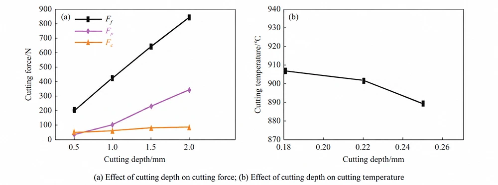
Research using the Taguchi-grey method examined cutting speed and depth during Ti-6Al-4V machining. The analysis indicated that cutting depth affected cutting force less strongly than cutting speed. Other experiments found that cutting force increased with cutting depth.
A greater cutting depth increases the cutting area, which raises friction and deformation forces. Some temperature measurements also found that tool temperature increased with cutting depth.
However, high-speed machining studies reported an opposite temperature trend. In those experiments, cutting temperature decreased as cutting depth increased.
Larger contact regions between workpiece, tool, and chips increased the available heat-dissipation area. This condition also promoted chip evacuation and reduced temperature.
Therefore, cutting-depth effects depend strongly on machining conditions and heat-transfer mechanisms. High-speed milling studies on TC17 found no obvious effect of cutting depth on surface microstructure.
No significant metallurgical phase transformation was observed. PCD tool studies found that cutting depths above 1 mm significantly reduced tool life.
Other research also identified a negative relationship between cutting depth and tool life.
Feed and Feed Rate
Feed represents tool displacement relative to the workpiece along the feed direction. Feed rate represents relative displacement per unit time along that direction.
Studies evaluated Ti-6Al-4V at feed rates of 80, 120, and 160 mm/min. Feed-direction cutting force initially decreased and then increased as feed rate rose.
Main cutting force, however, increased progressively. Feed rate affected the main cutting force more strongly than the feed-direction force.
Finite element simulations also evaluated feeds between 0.1 and 0.25 mm/r. Cutting temperature increased as feed increased.
Greater chip thickness and friction generated more heat within the shear zone. Similar simulations found higher milling temperatures when feed increased from 0.025 to 0.038 mm/r.
Feed per tooth also affects machined surface roughness. Roughness along the feed direction increased as feed per tooth increased. Surface roughness perpendicular to the feed direction remained almost unchanged.
Feed can also have a strong effect on tool life. Increasing feed from 0.08 to 0.13 mm/r reduced tool life from approximately 55 minutes to below 20 minutes. This result demonstrates the strong interaction between productivity and tool durability.
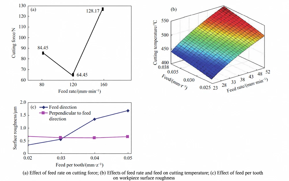
Cutting speed, cutting depth, and feed do not affect machining independently. Their interactions determine cutting force, temperature, surface quality, and tool service conditions.
Understanding these coupled effects has significant engineering value. It supports efficient production, improved component quality, and longer tool life.
Cutting Tools for Titanium Alloys
Tool Wear Mechanisms
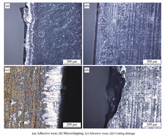
Typical tool wear mechanisms include adhesive wear, abrasive wear, oxidation wear, diffusion wear, coating damage, coating peeling, and micro-chipping. Several mechanisms can occur simultaneously during titanium machining.
Adhesive wear occurs when the workpiece, tool, and chips adhere under high temperature and pressure. Relative movement at adhesion points can tear material from the cutting tool.
Studies of Ti-6Al-4V at low cutting speeds found adhesive wear on several cemented-carbide tools.
High chemical affinity between titanium and carbide tools promotes chip adhesion. When adhered particles separate from the tool, they can remove tool material.
Adhesion during tool exit may also trigger micro-chipping during the next cutting engagement. Micro-chipping creates many small notches along the cutting edge.
These defects gradually reduce edge integrity and cutting performance. Abrasive wear occurs when hard particles enter tool-workpiece or tool-chip interfaces. These particles can create scratches and other surface defects.
Titanium alloy hardness and tool material properties directly affect this wear mechanism. Hard carbide particles formed from alloying elements can accelerate abrasive wear.
Tool coatings may also gradually detach during cutting. Coating loss can further intensify abrasive wear.
Oxidation wear develops when oxygen-affinity elements in the tool react with oxygen at high cutting temperatures.
These reactions produce oxide films. Weak or soft oxide films can break or peel away easily. New oxide layers then form, creating a repeated oxidation and removal cycle.
At higher Ti-6Al-4V cutting speeds, oxidation can become one of the dominant wear mechanisms.
Increasing temperature accelerates chemical reactions around the cutting edge. Diffusion wear involves elemental diffusion among chips, cutting tools, and workpieces.
This process changes the chemical composition of the cutting tool. Surface strength and hardness may decline as a result.
The weakened surface then becomes increasingly vulnerable to wear. Coated tools experience another failure mechanism when alternating stresses exceed coating-substrate bonding strength.
Damage first develops around the cutting edge. Continued loading causes damaged regions to spread toward the rake face.
This process can eventually produce severe tool wear. Titanium alloy cutting rarely produces only one wear mechanism. Multiple wear modes commonly occur simultaneously and interact with each other.
Tool and Coating Materials
Tool selection should consider several important material characteristics. Cutting tools require sufficient hardness, strength, toughness, and chemical stability against the workpiece.
Common tool materials include high-speed steel, cemented carbide, coated tools, ceramics, and superhard materials.
Each category offers different performance advantages and limitations. Higher cutting speeds and precision requirements have increased demands on tool and coating technologies.
Advanced coatings can improve wear resistance under demanding titanium machining conditions. One ultrafine-grained gradient carbide tool uses Co10Ti3 with a TiAlCrN coating. Tests showed strong wear resistance during high-speed titanium machining.
Its wear was comparable to that of a GC1105-coated tool. Wear reached only about 30% of a GC4225 tool and 50% of a YBG202-coated turning tool.
Researchers have also designed micro-grooved YG8 and PCD tools for cryogenic Ti-6Al-4V cutting. Micro-grooves can reduce friction between the cutting tool and chips.
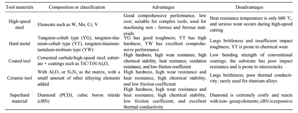
Table 2. Comparison of Different Cutting Tool Materials
Challenges and Future Development Directions
Titanium alloy cutting continues to move toward higher speeds and greater precision. Meanwhile, rapid development of advanced titanium alloys introduces several new machining challenges.
First, only a small number of companies currently possess near-high-speed cutting capabilities. Mainstream cutting speeds remain concentrated between 50 and 100 m/min.
This range remains substantially below future high-speed machining requirements. Equipment, cutting tools, and process control therefore require further development.
Second, constitutive models for titanium alloy cutting should integrate experimental validation with numerical simulation.
Models should systematically consider coupling between macroscopic and microscopic parameters. Multi-scale and multidimensional approaches can further improve model rationality and predictive accuracy.
This development is important for increasingly complex machining environments. Third, workpiece surface quality remains a central indicator of machining performance.
Existing evaluation systems cannot fully account for all influencing factors. Developing a systematic surface-quality evaluation framework therefore remains an important research direction.
Such systems should better connect machining conditions with final component performance.
Conclusion
Low thermal conductivity and high chemical activity make titanium alloys difficult to machine. These properties complicate dimensional accuracy, surface quality, temperature control, and tool-life management.
Researchers have developed high-speed cutting, ultrasonic vibration-assisted cutting, turn-milling, and cryogenic cutting to address these challenges.
These technologies can improve accuracy, efficiency, surface integrity, or tool life. Researchers also use conventional experiments, Hopkinson pressure-bar testing, constitutive modeling, and numerical simulations.
Together, these methods provide a broader understanding of titanium alloy cutting behavior. Titanium alloys commonly generate serrated chips during machining.
Adiabatic shear and periodic fracture remain the two major theories explaining their formation. Cutting speed, depth, and feed do not act independently.
Their coupled effects determine cutting forces, temperatures, machined surface quality, and tool life. Tool wear also rarely follows a single mechanism during titanium alloy machining. Adhesive, abrasive, oxidation, diffusion, coating damage, and micro-chipping mechanisms can coexist.
Future development should therefore integrate advanced cutting technologies, improved predictive models, optimized process parameters, and better tool materials. These advances can support efficient, precise, and reliable titanium alloy machining.