The jaw crusher serves as a key crushing equipment in mining, building materials and metallurgy industries.
Its movable jaw bearing housing endures continuous alternating impact and eccentric loads.
The bearing housing bore is therefore prone to wear failure.
Once the bore wear exceeds 0.1 mm, the bearing outer ring will spin and the fit clearance will grow.
This triggers a chain of faults: amplified main shaft vibration, abnormal bearing temperature rise, and uneven jaw plate wear.
In severe cases, this can result in major accidents such as main shaft fracture and frame cracking.
Traditional methods for repairing bearing housing bores primarily include manual arc surfacing, electroplating, and polymer composite repairs.
Surfacing repairs are prone to generating welding stresses and deformation, causing the bearing housing bore’s geometric tolerances to exceed specifications;
Electroplated repair layers have limited thickness—generally not exceeding 0.3 mm—and cannot meet the repair requirements for severe wear;
Polymer composite repairs have low bond strength and struggle to withstand the impact loads of crushers.
The boring and bushing repair process follows three steps.
First, we bore the worn bore of the bearing housing to the target size.
Next, we press-fit a steel sleeve into the machined bore with an interference fit.
Finally, we precision-bore the inner hole of the sleeve to match the bearing’s mounting dimension.
This method efficiently recovers the geometric accuracy and load capacity of the bearing housing.
It is now the mainstream repair process for bearing housing bores of large jaw crushers.
Failure Analysis and Inspection of Bearing Housing Bore Wear
Wear Mechanisms and Failure Modes
Wear in the bearing housing bore of a jaw crusher is primarily the result of a combined effect of adhesive wear and abrasive wear.
During crusher operation, there is slight relative sliding between the outer ring of the bearing and the bearing housing bore.
Under contact pressure, microscopic metal protrusions on the contact surface undergo adhesion and shearing, resulting in material transfer and the formation of adhesive wear.
At the same time, dust particles in the lubricating oil and metal debris generated by wear enter the mating surfaces, accelerating the process of abrasive wear.
The primary failure modes of the bearing housing bore include out-of-tolerance cylindricity of the inner bore, coaxiality deviation, surface scratches, and pitting.
Among these, out-of-tolerance cylindricity is the most common failure mode, primarily caused by off-center loading;
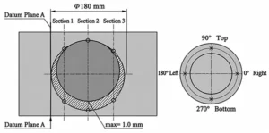
We usually find wear concentrated in the lower half of the bearing housing bore, and the maximum wear can reach 1.0 mm.
Coaxiality deviation mainly originates from installation errors and foundation settlement after long-term service.
It introduces extra bending moments on the bearing. This accelerates wear of both the bearing and bearing housing.
A typical morphology of bearing housing bore wear is shown in Figure 1.
Inspection and Evaluation of Wear
We inspect the wear of the bearing housing bore with an inside micrometer and a dial indicator.
First, using the machined reference surface of the bearing housing as the measurement reference, select three cross-sections along the axial direction of the bearing housing bore.
At each cross-section, measure four points evenly spaced around the circumference and record the inside diameter dimensions at each point.
Calculate the difference between the maximum and minimum inner diameters within the same cross-section; this represents the cylindricity error for that cross-section.
Calculate the difference in inner diameter measurements in the same direction across different cross-sections; this represents the concentricity error of the bearing housing bore.
Operators can sustain normal operation by adjusting bearing preload if the wear on the bearing housing bore stays below 0.1 mm.
Boring and bushing insertion serve as the proper repair method for wear ranging from 0.1 mm to 0.8 mm.
We replace the bearing housing when wear exceeds 1.2 mm or cracks and deformation occur.
Table 1 shows the inspection results for the moving jaw bearing housing bore of a PE600×900 jaw crusher at a certain mine.
The maximum wear was 0.65 mm, and the cylindricity error was 0.12 mm, meeting the criteria for bore boring and sleeve insertion repair.
Measurement Section | Measurement Direction | Inner Diameter (mm) | Wear Amount (mm) | Cylindricity Error (mm) |
|---|---|---|---|---|
Section 1 | Top | 180.52 | 0.52 | 0.11 |
Bottom | 180.63 | 0.63 | 0.11 | |
Left | 180.55 | 0.55 | 0.11 | |
Right | 180.58 | 0.58 | 0.11 | |
Section 2 | Top | 180.54 | 0.54 | 0.12 |
Bottom | 180.66 | 0.66 | 0.12 | |
Left | 180.57 | 0.57 | 0.12 | |
Right | 180.60 | 0.60 | 0.12 | |
Section 3 | Top | 180.51 | 0.51 | 0.10 |
Bottom | 180.61 | 0.61 | 0.10 | |
Left | 180.53 | 0.53 | 0.10 | |
Right | 180.56 | 0.56 | 0.10 |
Table 1. Measurement Data of Bearing Housing Bore Wear in the PE600 × 900 Jaw Crusher
Design of the Boring and Sleeve Insertion Repair Process
The complete process flow for the boring and sleeve insertion repair process is shown in Figure 2.
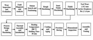
Pre-Repair Preparation
Before repair, first clean the oil, rust, and scale from the surface of the bearing housing.
Use magnetic particle testing to inspect the bearing housing for hidden defects such as cracks.
Secure the bearing housing to the boring machine table.
Take the original machined datum surface of the bearing housing as the positioning reference.
Adjust the worktable to align the axis of the bearing housing bore with the boring machine spindle axis, and limit the coaxiality error within 0.02 mm.
Drill two Φ8 mm locating pin holes on the end face of the bearing housing bore.
These holes act as positioning datums for later bushing installation and stop the bushing from rotating during press fitting.
Optimization of Boring Process Parameters
We divide the boring process into three stages: rough boring, semi-finish boring, and finish boring.
Rough boring mainly removes the majority of the worn layer.
Semi-finish boring reserves a 0.3–0.5 mm machining allowance for finish boring.
Finish boring guarantees the dimensional accuracy and surface roughness of the bore.
The selection of boring cutting parameters directly affects machining efficiency and surface quality.
The recommended cutting parameters for different bore diameter ranges are shown in Table 2.
Bore Diameter Range (mm) | Cutting Speed (m/min) | Feed Rate (mm/rev) | Depth of Cut (mm) | Tool Material |
|---|---|---|---|---|
100–200 | 60–80 | 0.15–0.25 | 0.5–1.0 | YT15 |
200–300 | 50–70 | 0.20–0.30 | 0.8–1.2 | YT15 |
300–400 | 40–60 | 0.25–0.35 | 1.0–1.5 | YT15 |
Table 2. Cutting Parameters for Boring the Bearing Housing Bore
A floating boring tool is used for precision boring, achieving a surface roughness (Ra) of 1.6 μm or less.
After boring, we inspect the dimensional accuracy and geometric tolerances of the bore.
We control the cylindricity error within 0.02 mm and limit the end-face runout to 0.02 mm.
Design and Machining of Sleeve Inserts
The sleeve insert is made of 45 steel, which, after quenching and tempering, has a hardness (HB) of 220–250 and is well-matched to the mechanical properties of the bearing housing material.
The wall thickness of the insert is determined based on the expected wear rate and is generally set at 5–10 mm.
If the wall is too thin, the insert may deform; if too thick, it will increase machining difficulty and cost.
We design an interference fit between the outer diameter of the insert and the bored hole.
The formula for calculating the interference is:

In the formula: Δ is the interference fit, in mm; K is the safety factor, ranging from 0.8 to 1.0; d is the mating diameter, in mm;
σs1 is the yield strength of the sleeve, in MPa; E1 is the elastic modulus of the sleeve, in MPa;
σs2 is the yield strength of the bearing housing, in MPa; E2 is the elastic modulus of the bearing housing, in MPa.
The recommended interference fits for different bore diameters are shown in Table 3.
A machining allowance of 0.3–0.5 mm is reserved for the inner bore of the sleeve;
Operators control the surface roughness Ra of the outer circular surface to 3.2 μm or less, and keep the cylindricity error below 0.015 mm.
Fit Diameter (mm) | Interference Allowance Range (mm) | Heating Temperature (°C) |
|---|---|---|
100–150 | 0.08–0.12 | 180–200 |
150–200 | 0.12–0.16 | 190–210 |
200–250 | 0.16–0.20 | 200–220 |
Table 3. Recommended Interference Fit Allowances and Heating Temperatures for Different Bore Diameters
Interference Fit Assembly Process
The sleeve is assembled using the hot-fitting method.
Operators use a box-type resistance furnace as the heating equipment, and determine the heating temperature according to the interference and mating diameter.
The calculation formula is as follows:

In the equation: T is the heating temperature, in °C;
T₀ is the ambient temperature, in °C; α is the linear expansion coefficient of 45 steel, taken as 11.5 × 10⁻⁶ °C⁻¹.
Operators raise the temperature slowly during heating and keep the heating rate no higher than 50 °C/h.
They calculate the holding time at 2 to 3 minutes per millimeter of wall thickness to ensure uniform temperature distribution inside the liner.
Quickly align the heated insert with the locating pin hole and press it smoothly into the bored hole, maintaining uniform pressure throughout the process to avoid impact.
After the sleeve cools to room temperature, it undergoes natural aging for 24 hours.
A floating boring tool is then used for finish boring on the inner hole of the sleeve to reach the bearing fitting size.
Operators control the surface roughness Ra below 1.6 μm.
Repair Accuracy Control and Inspection Methods
Key Points for Geometric Tolerance Control
The geometric tolerances of a bearing housing bore after repair directly affect the bearing’s operating condition, with cylindricity, concentricity, and end-face runout being the most critical control parameters.
Large cylindricity errors distribute stress unevenly over the bearing outer ring and speed up bearing wear.
Out-of-tolerance concentricity errors induce extra bending moments on the main shaft and trigger vibration across the whole machine.
Excessive face runout introduces axial clearance in the bearing and impairs the discharge accuracy of the crusher.
During boring operations, multiple passes are used to minimize deformation caused by cutting forces, and the depth of cut during finish boring does not exceed 0.2 mm.
Prior to sleeve assembly, the geometric and positional tolerances of the bored hole and the sleeve are strictly inspected to ensure the machining quality of the mating surfaces.
After assembly, the inner bore of the sleeve is precision-bored with the original datum surface of the bearing housing as the measurement reference.
This step ensures the geometric and positional tolerances of the inner bore satisfy the specifications.
Accuracy Inspection After Assembly
After repair, we measure the inner bore size of the sleeve with an inside micrometer.
A dial indicator and magnetic base are used to test cylindricity, coaxiality and end-face runout.
See Figure 3 for the accuracy inspection of the bearing housing bore after repair.
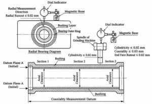
During measurement, we secure the dial indicator to the lathe spindle and keep the indicator needle perpendicular to the measured surface.
Slowly rotate the spindle and record the maximum and minimum readings on the dial indicator;
The difference between these two readings represents the form and position error of the measured surface.
The geometric tolerance requirements for the repaired bearing housing bore are as follows: for bore diameters of Φ100–200 mm, cylindricity ≤ 0.02 mm, concentricity ≤ 0.03 mm, and end face runout ≤ 0.02 mm.
A coordinate measuring machine (CMM) is used to conduct a comprehensive inspection of the repaired bearing housing bore to verify the effectiveness of the precision control measures.
Engineering Application and Performance Verification
The above process was applied to the repair of the bearing housing bore of a PE600×900 jaw crusher at a certain mine.
The original dimensions of the bearing housing bore were Φ180H7, with a wear depth of 0.65 mm.
After boring, the dimensions were Φ190H7; the outer diameter of the insert was Φ190r6, with an interference fit of 0.14–0.16 mm.
The heating temperature was 200 °C, and the holding time was 30 min.
After we finished the repair, we inspected the accuracy of the bearing housing bore.
The results showed that the dimensional accuracy of the insert’s inner bore was Φ180H7, with a cylindricity error of 0.015 mm, a concentricity error of 0.022 mm, and an end-face runout error of 0.018 mm—all of which met the accuracy requirements.
Technicians installed the repaired bearing housing on the crusher and carried out no-load and load test runs.
The crusher’s vibration velocity was 2.3 mm/s, and the bearing temperature rise was 32 °C, both within acceptable limits.
After 12 months of operation, we re-inspected the bearing housing bore.
The maximum wear was 0.08 mm, which was lower than the 0.12 mm wear observed in a new bearing housing over the same period.
The total cost of this repair process was approximately 30% of the cost of replacing the bearing housing, and the repair cycle was only 3 days, significantly reducing equipment maintenance costs and downtime.
Conclusion
The boring and bushing repair process can effectively recover the geometric accuracy and load capacity of jaw crusher bearing housing bores.
It features low cost, short repair cycle and high reliability.
By optimizing boring cutting parameters, designing the interference fit properly, and tightly controlling geometric and positional tolerances, we can limit the geometric and positional errors of repaired bores within 0.03 mm.
Engineering applications show that bearing housings repaired by this process can achieve over 85% of the service life of new components.
This process delivers favorable economic benefits and is suitable for wide promotion.