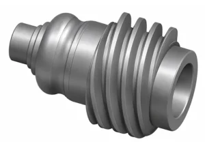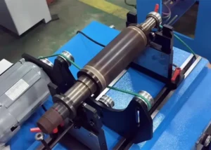
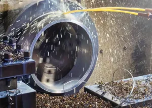
Rotary components (such as flanges, gears, and impellers) are among the key components that enable motion and load transfer in various types of mechanical equipment;
Their dimensional and geometric tolerances directly affect the assembly quality and service life of the products;
Among these, flanges are the most widely used disc-shaped parts.
Engineers extensively employ them in critical connection points such as petrochemical pipelines, aerospace vehicle docking, and ship power transmission systems.
They must strictly control the flatness of sealing surfaces, the positional accuracy of mounting bolt holes, and the coaxiality of inner and outer circles;
Any deviation from tolerance will result in seal failure or stress concentration.
Existing inspection methods rely primarily on CMMs and specialized inspection fixtures;
However, they suffer from bottlenecks such as low efficiency, high costs, and the inability to perform in-line inspection.
In recent years, machine vision and laser measurement technologies have advanced rapidly, providing a non-contact, highly efficient inspection approach for flange-type components.
Nevertheless, a single sensor remains insufficient for parts with complex geometric features and multi-source errors.
To address these issues, this paper proposes a multi-source information inspection method that integrates rotating line structured light, machine vision, and a contact probe.
Combined with error decoupling and hierarchical compensation strategies, we carry out a systematic study with flanges as test objects.
We aim to realize high-precision, high-efficiency dimensional tolerance inspection.
Current Status and Challenges in Flange Dimension Tolerance Inspection
The primary inspection criteria for flanges include outer diameter, inner diameter, bolt hole center circle diameter (PCD), flatness error of the sealing surface, end face perpendicularity error, and coaxiality error between the inner and outer circles.
These factors interrelate and can all affect the performance, reliability, and safety of the equipment.
For non-contact inspection methods, we have developed a machine vision measurement system based on Zernike moment sub-pixel edge detection technology to measure flange dimensions.
While the measurement accuracy for outer and inner diameters meets industrial requirements, it cannot directly measure geometric tolerances such as flatness;
Rotating line-scan structured light can achieve 3D reconstruction and flatness evaluation of large-sized flanges, with a measurement uncertainty of approximately 0.17 mm;
However, it is susceptible to reflections from the workpiece surface and external light sources.
Most of the above inspection methods target only one feature or a single dimension.
They lack comprehensive inspection capacity.
Besides, they cannot effectively compensate for systematic errors, such as position eccentricity and inclined reference planes.
To address these shortcomings, this paper proposes a method that combines multiple sensing technologies with online error compensation.
Precision Inspection Method Based on Multi-Source Information Fusion
Overall Architecture of the Inspection System
The inspection system designed in this paper consists of a precision rotary platform, a line-scan structured light sensor, a high-resolution industrial camera, a contact-type inductive probe, and a control unit (see Figure 1).
The rotary platform drives the flange to rotate at a constant angular velocity;
The line-scan laser sensor projects laser stripes radially onto the outer contour and end face of the flange;
The industrial camera captures two-dimensional images from directly above to obtain global geometric information;
And the contact probe is used to verify critical dimensions and calibrate the sensors. The system registers and fuses all measurement data under a unified coordinate system.
This architecture takes advantage of line-scan 3D reconstruction. It integrates snapshot positioning from machine vision and full-field measurement.
Operators adopt contact measurement to guarantee precision. This setup breaks the constraints of conventional non-contact measurement, which relies heavily on the surface characteristics of the test piece.
Key Inspection Technologies
1. Principle and Implementation of Rotating Line Structured Light 3D Reconstruction
Rotating line structured light 3D reconstruction serves as one core inspection technology.
It is built on the laser triangulation principle. A line laser projects light stripes onto the flange surface.
An industrial camera captures the deformed stripe images.
A Gaussian filter combined with the Maximum Stable Extremum Region (MSER) operator is then used to extract the center points of the laser stripes at the sub-pixel level;
This method achieves an extraction accuracy of 10 μm. We adopt rotational scanning for data acquisition.
Using rotation axis parameters (direction vector and origin), we register multi-angle point clouds into one unified reference frame.
We obtain a complete 3D point cloud of the flange surface and use this point cloud to calculate flatness and coaxiality.
2. Machine Vision Workflow for Global Dimensional Measurement
Machine vision is used for global dimensional measurement. An industrial camera captures images of the flange end face.
The images go through grayscale conversion and median filtering to suppress noise.
Otsu adaptive thresholding generates a binary image. The Canny operator performs preliminary edge detection.
An improved Zernike moment subpixel algorithm then extracts high-precision edge coordinates.
Finally, we realize automatic evaluation of PCD and hole spacing through least-squares circular fitting.
The processing time for a single frame in visual measurement is in the order of hundreds of milliseconds, making it suitable for rapid in-line inspection.
3. Multi-Sensor Calibration and Coordinate Unification
For multi-sensor data fusion and coordinate unification, each sensor works in an independent coordinate system, so we need precise spatial calibration.
Finally, we convert all measurement data into a unified workpiece coordinate system that references the flange reference end face.
Visual measurement provides overall dimensional and positional information, while structured light scanning captures point clouds of the end face and contour shape;
A contact probe is used to verify specific hole diameters and thicknesses.
The combined use of these three methods not only increases measurement speed but also effectively ensures the accuracy of critical dimensions, thereby yielding reliable compensation data.
Analysis of Multi-Source Errors and Hierarchical Compensation Strategies
Identification of Error Sources
These measurement platforms produce three types of error sources.
Sensors introduce the first category of errors: camera lens distortion, laser nonlinearity, and probe radius deviation.
Workpieces trigger the second error group, which covers variable surface roughness, eccentric or tilted clamping, and inconsistent material reflectivity.
Ambient conditions create the third error type, dominated by temperature drift and vibration interference.
Among all error sources, eccentric and tilted mounting of the flange on the rotary stage dominates the systematic error.
It directly introduces radial dimensional measurement errors and shifts the evaluation reference for the end face.
Accordingly, we must design compensation algorithms to address this type of error.
Compensation for Eccentricity Errors Based on Dynamic Polar Coordinate Correction
To solve the eccentricity problem, this paper adopts a compensation method validated in train wheel inspection.
During rotational scanning, the system collects polar coordinates of a selected point on the flange outer circumference.
It calculates the circle center for each sampling moment using the least-squares method. The system records the center’s trajectory over one full rotation.
It implements radius and angular compensation along the rotation direction according to this trajectory.
This method cuts radial deviations induced by eccentricity from above 0.5 mm to below 0.05 mm.
No mechanical centering fixture is required. Its performance greatly outperforms conventional compensation schemes based on fixed reference points.
The corrected point cloud accurately reflects the true geometric position of the flange. It supports subsequent form and position tolerance evaluation and delivers high-quality raw measurement data.
Compensation for Reference and Tilt Errors
The evaluation of end-face perpendicularity and flatness is based on a correct reference axis.
If we treat the rotary table axis as the measurement reference axis, the tilt angle and rotational errors inherent to the rotary table will enter the final evaluation.
Referring to methods for eliminating reference errors when inspecting multistage rotors, this section determines the reference axis using the geometric features of the flange itself.
Specifically, the coordinates from end-face points and outer-circumference points are processed together.
The least-squares method computes the actual rotation axis of the flange. This axis defines the reference direction for perpendicularity and flatness tolerance evaluation.
Meanwhile, a normal-direction compensation strategy is applied. It offsets systematic geometric errors originating from probe radius, laser stripe width and other related factors.
This involves moving a certain distance (equal to the probe radius) along the normal to the surface of the part being measured to eliminate displacement errors caused by the probe’s dimensions.
Experimental results show that the flatness and perpendicularity after reference error compensation agree closely with coordinate measuring machine (CMM) readings.
The deviation stays below 0.005 mm.
Multi-Level Compensation Process and Implementation
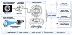
To address the aforementioned sources of error, a three-level nested compensation method is proposed (see Figure 2) .
Level 1 (Macro Compensation) targets fixed errors including camera distortion and laser source nonlinearity.
It uses sensor calibration results and converts data from all sensors into a unified rigid-body coordinate system.
Level 2 (Attitude Compensation) corrects coaxiality deviations in real time through polar coordinate transformation.
This module removes reference tilt errors by fitting the practical axis of the workpiece.
Level 3 (Fine Compensation) calculates radius or width compensation along the normal vector of each measurement point.
It filters residual signals with a low-pass filter to attenuate random noise.
The three compensation levels are progressive and non-redundant, ultimately yielding high-precision measurement results that closely approximate the true value.
Experimental Validation and Application Results
To verify the effectiveness of the method proposed in this paper, a standard DN100 flange (material: 304 stainless steel) was selected for comparative testing.
The following dimensions were measured: outer diameter, inner diameter, flatness of the sealing surface, bolt hole center circle diameter (PCD), and end face perpendicularity;
Reference values were obtained through multiple measurements using a Hexagon coordinate measuring machine (MPE_E = 0.002 mm) in a temperature-controlled chamber.
The test specimen was measured 10 times in a laboratory maintained at 20 ± 0.5°C, and the average value was taken as the reference value. The test results are shown in Table 1.
Measurement Parameter | Reference Value | Proposed Method | Measurement Deviation | Traditional Vision Method | Line Structured-Light Method |
|---|---|---|---|---|---|
Outer Diameter | 200.025 | 200.038 | 0.013 | 0.045 | 0.062 |
Inner Diameter | 100.012 | 100.000 | −0.012 | 0.038 | 0.051 |
Sealing Surface Flatness | 0.048 | 0.051 | 0.003 | 0.072 | 0.065 |
Bolt Hole PCD | 180.040 | 180.055 | 0.015 | 0.043 | 0.070 |
End-Face Perpendicularity | 0.022 | 0.020 | −0.002 | 0.035 | 0.045 |
Note: All dimensions and measurement values are in millimeters (mm). PCD stands for Pitch Circle Diameter.
Table 1. Comparison of Flange Dimension Measurement Results (mm)
As shown in Table 1, the absolute values of the measurement errors for the method described in this paper are less than 0.015 mm for all parameters.
Furthermore, the flatness and perpendicularity errors are approximately one-tenth of those obtained using only visual methods (error > 0.035 mm) and only line structured light methods (error > 0.045 mm), respectively.
Specifically, the flatness measurement error is 0.003 mm, while the measurement deviation for perpendicularity is −0.002 mm.
This is achieved through multi-sensor data fusion and a hierarchical error compensation strategy.
Additionally, a single inspection cycle (including scanning, image processing, data fusion, and compensation calculations) takes approximately 45 seconds.
Compared to a conventional measurement on a coordinate measuring machine (which takes about 8 minutes), this represents a more than tenfold increase in efficiency.
Furthermore, since no re-clamping is required, the method meets the requirements for rapid inspection and high precision necessary for in-line inspection.
Conclusion
This paper focuses on flanges and investigates the precise measurement of dimensional tolerances and error compensation for wheel-type components.
This method integrates rotating line structured light 3D reconstruction, machine vision subpixel technology, and contact probe calibration for joint analysis.
It breaks through the performance limitations of using a single sensor alone.
Furthermore, to tackle major systematic errors including eccentric placement and inclined reference planes, this study puts forward a layer-by-layer compensation method.
It adopts dynamic correction under polar coordinates and takes the workpiece itself as the reference datum.
The effectiveness of this method was verified through experiments. The results show that the proposed method achieves measurement accuracy better than 0.015 mm.
Meanwhile, its inspection efficiency is more than one order of magnitude higher than that of traditional CMMs. This method has great practical engineering value.