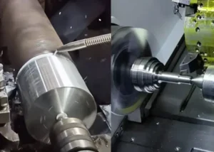
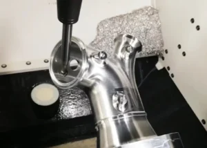
In turning operations, engineers frequently machine workpieces with inner and outer circular surfaces that require a precision grade of Class 2 or higher.
However, due to various factors—such as cutting heat, friction between the workpiece and the tool causing tool wear, and the repeatability of the square tool holder’s positioning—it is difficult to guarantee consistent quality.
To achieve precise, minute cuts, we utilize the relationship between the opposite sides and the hypotenuse of a triangle in turning operations.
By rotating the longitudinal tool post by a specific angle, we can precisely set the lateral depth of cut for the turning tool.
This method saves labor and time, ensures product quality, and improves productivity.
On a typical C620 lathe, each division on the small tool post scale corresponds to 0.05 mm.
To obtain a lateral depth of cut of 0.005 mm, consult a sine table:
sinα = 0.005/0.05 = 0.1; α = 5° 44′
Therefore, by adjusting the tool post to 5° 44′, each increment of the longitudinal scale on the tool post corresponds to a micro-adjustment of 0.005 mm in the lateral depth of cut of the turning tool.
Three Examples of Reverse Turning Technology Applications
Long-term production experience has demonstrated that reverse cutting technology can yield excellent results in specific turning operations.
The following are some practical examples:
Reverse Cutting of Threads in Martensitic Stainless Steel Parts
When machining internal and external threads with pitches of 1.25 and 1.75 mm, the division of the lathe lead by the workpiece pitch results in a non-integer value.
If the operator retracts the tool after lifting the mating nut handle during threading, misaligned threads often occur.
Since standard lathes generally lack a misalignment disc device, and fabricating a custom set takes considerable time, operators often adopt the following method when machining threads with these pitch values.
The method used is low-speed conventional turning.
Since high-speed thread cutting does not allow sufficient time to retract the tool, production efficiency is low.
This method is prone to tool chipping during turning and results in poor surface roughness.
This issue is particularly pronounced when low-speed cutting is applied to martensitic stainless steels such as 1Cr13 and 2Cr13.
The “three-reverse” cutting method—involving reverse tool mounting, reverse rotation, and opposite feed direction—developed through practical experience yields excellent overall cutting results.
This method allows for thread cutting at high speeds; since the tool moves from left to right as it retracts from the workpiece, it eliminates the problem of the tool being unable to retract during high-speed thread cutting.
The specific method is as follows:
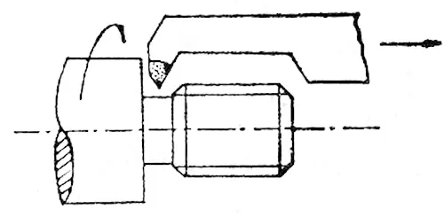
When turning external threads, grind a tool similar to an internal thread turning tool (Fig. 1);
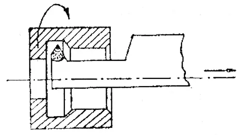
When cutting internal threads, grind a reverse-cut internal threading tool (Fig. 2).
Before machining, slightly tighten the spindle of the reverse friction disc to ensure the correct speed during reverse startup.
Align the threading tool, close the clamping nut, and start the forward rotation at low speed until reaching the clearance groove.
Then, advance the threading tool to the appropriate cutting depth before switching to reverse rotation.
At this point, the tool will feed from left to right at high speed.
After several passes using this method, you can produce threads with excellent surface roughness and high precision.
Reverse Knurling
During traditional forward-rotation knurling, metal chips and debris easily enter the space between the workpiece and the knurling tool, causing excessive stress on the workpiece and resulting in irregular patterns, damaged knurling, or ghosting.
By adopting the new method of reverse-rotation knurling with the lathe spindle rotating in a flat position, the defects associated with forward-rotation operations can be effectively prevented, yielding excellent overall results.
Reverse Turning of Internal and External Tapered Pipe Threads
When turning internal and external tapered pipe threads with relatively low precision requirements and in small batches, it is possible to dispense with jigging devices and directly employ a new method involving reverse cutting and reverse tool mounting.
While cutting, continuously adjust the tool laterally by hand (when turning external tapered pipe threads, move from left to right;
Adjusting the tool laterally from the larger diameter to the smaller diameter makes it very easy to control the depth of cut) . This is due to the preload generated during the tapping process.
The scope of application for this new reverse-cutting technique in turning technology is becoming increasingly widespread, and it can be flexibly adapted to various specific situations.
A New Method for Drilling Small Holes and Tool Innovations
In turning operations, when drilling holes smaller than 0.6 mm, the small diameter of the drill bit results in poor rigidity and limits cutting speed.
Furthermore, since the workpiece material is heat-resistant alloy or stainless steel, cutting resistance is high.
Consequently, if mechanical feed is used during drilling, the drill bit is highly prone to breaking.
The following describes a simple and effective tool and manual feed method.
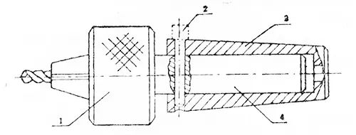
First, modify the original drill chuck into a straight-shank floating type.
During operation, simply clamp the small drill bit into the floating drill chuck to drill smoothly.
Because the rear of the drill bit has a straight-shank sliding fit, it can move freely within the pull sleeve.
When drilling small holes, gently hold the drill chuck by hand to achieve manual micro-feed, allowing you to quickly drill the small hole while ensuring quality and extending the service life of the small drill bit.
The modified multi-purpose drill chuck can also be used for tapping small-diameter internal threads and reaming (if drilling slightly larger holes, simply insert a stop pin between the pull sleeve and the straight shank), as shown in Figure 3.
Vibration Control in Deep-Hole Machining
In deep-hole machining, due to the small hole diameter and the slender shank of the boring tool, vibration is inevitable when turning deep-hole parts with diameters ranging from Φ30 to 50 mm and depths of approximately 1,000 mm.
To prevent shank vibration, the simplest and most effective method is to attach two support blocks (made of materials such as cloth-reinforced phenolic resin) to the shank body, sized exactly to match the hole diameter.
During the cutting process, the fabric-reinforced phenolic blocks serve as positioning supports, preventing the tool shank from vibrating and enabling the production of high-quality deep-hole parts.
Preventing Breakage of Small Center Drills
In turning operations, when drilling a center hole smaller than 1.5 mm in diameter, the center drill is highly prone to breaking.
A simple and effective method to prevent breakage is to leave the tailstock unlocked while drilling the center hole, allowing the tailstock’s own weight and the friction between it and the machine bed to drive the drilling process.
When cutting resistance becomes too great, the tailstock will automatically retract, thereby protecting the center drill.
Vibration Control in the Turning of Thin-Walled Workpieces
During the turning of thin-walled workpieces, vibrations often occur due to the workpiece’s low rigidity.
This is particularly pronounced when turning stainless steel and heat-resistant alloys, resulting in extremely poor surface finish and a shortened tool life.
The following are some of the simplest vibration control methods used in production.
(1) When turning the outer diameter of a hollow, slender stainless steel tube workpiece, fill the bore with wood shavings and pack them tightly.
Simultaneously, plug both ends of the workpiece with phenolic resin-impregnated cloth plugs.
Then, replace the support jaws on the tailstock with phenolic resin-impregnated cloth support blocks.
After adjusting the required arc, proceed with the turning operation on the hollow, slender stainless steel rod.
This simple method effectively prevents vibration and deformation of the hollow, slender rod during machining.
(2) When turning the inner bore of thin-walled workpieces made of heat-resistant (high-nickel-chromium) alloys, severe resonance occurs during the cutting process due to the workpiece’s low rigidity and the slender tool shank, which can easily damage the cutting tool and result in scrap.
Wrapping the workpiece’s outer circumference with shock-absorbing materials such as rubber strips or sponge can effectively prevent vibration.
(3) When turning the outer diameter of thin-walled sleeve-type workpieces made of heat-resistant alloys, vibrations and deformation are highly likely to occur during machining due to a combination of factors, including the high cutting resistance of heat-resistant alloys.
By inserting rubber, cotton fibers, or other materials into the workpiece bore and then clamping it securely by pressing against both end faces, vibrations and workpiece deformation during machining can be effectively prevented, resulting in high-quality thin-walled sleeve-type workpieces.
Additional Anti-Vibration Tools
Due to the low rigidity of slender shaft-type workpieces, vibrations are likely to occur during multi-groove cutting, resulting in poor surface finish and tool damage.
Fabricating a set of additional anti-vibration tools can effectively resolve the vibration issues encountered when machining slender workpieces (see Figure 4).
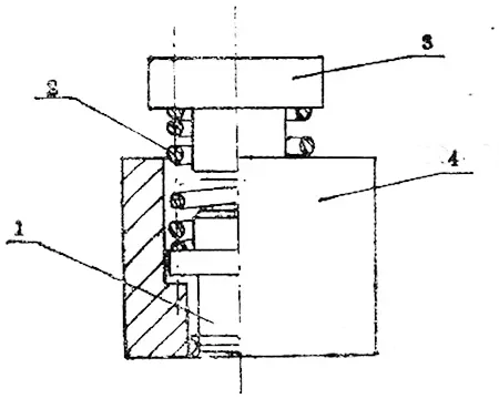
Before starting work, mount the homemade anti-vibration device in a suitable position on the square tool holder.
Then, install the required grooved turning tool on the square tool holder, adjust the distance and spring compression, and you are ready to begin.
When the turning tool engages the workpiece, the anti-vibration device simultaneously presses against the workpiece surface, providing effective vibration damping.
Honing for Finishing Difficult-to-Machine Materials
When precision turning difficult-to-machine materials such as high-temperature alloys and hardened steel, the surface roughness of the workpiece is required to be between Ra 0.20 and 0.05 μm, and dimensional accuracy must also be high.
The final finishing operation is typically performed on a grinding machine.
By making a simple set of honing tools and a honing wheel yourself, replacing the fine grinding process with honing on a lathe can yield significant economic benefits.
Quick-Change Mandrels
In turning operations, it is common to machine the outer diameter and chamfer the guide taper of various types of bearing assemblies.
Due to large production batches, the time spent mounting, dismounting, and changing tools during the machining process often exceeds the actual cutting time, resulting in low production efficiency.
The quick-change mandrel and single-tool, multi-edge (carbide) turning tool described below can reduce auxiliary time and ensure product quality when machining various bearing assembly parts.
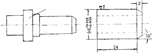
The manufacturing method is as follows.Fabricate a simple, slightly tapered mandrel.
The principle relies on a minimal 0.02 mm taper at the rear of the mandrel; once the bearing sleeve is mounted, friction holds the part securely in place.
Using a single-flute, multi-edge turning tool, machine the outer diameter, then chamfer a 15° cone angle.
After stopping the machine, use a wrench to eject the part—a process that is both fast and effective, as shown in Figure 5.
Turning of Hardened Steel Parts
1. Key Examples of Turning Hardened Steel Parts
① Remanufacturing (repair after fracture) of hardened W18Cr4V high-speed steel broaches
② Fabrication of custom non-standard thread plug gauges (hardened parts)
③ Turning of hardened parts and spray-coated parts
④ Turning of polished plug gauges for hardened parts
⑤ Thread polishing taps modified from high-speed steel cutting tools
For the hardened parts and various difficult-to-machine materials encountered in production as described above, selecting appropriate tool materials, cutting parameters, tool geometries, and operating methods can yield excellent overall economic results.
For example, when regenerating a square-end broach after it has broken, remanufacturing a new one would not only involve a long production cycle but also high costs.
Instead, at the base of the broken broach, we selected carbide inserts such as YM052, ground them to a negative rake angle of -6° to -8°, and carefully polished the cutting edge with an oilstone before turning.
The cutting speed was set to V = 10–15 m/min. After turning the outer diameter, a clearance groove is machined, followed by thread turning (divided into rough and finish turning).
After rough turning, the tool must be re-ground and re-polished before performing finish turning of the external threads.
Next, an internal thread for connecting the drawbar is machined, and the tool is lightly finished after assembly.
A square-end broach that was reported as scrap due to breakage is restored to like-new condition after turning.
2. Selection of Cutting Tool Materials for Turning Hardened Parts
① New grades of cemented carbide inserts, such as YM052, YM053, and YT05, typically operate at cutting speeds below 18 m/min, achieving a workpiece surface roughness of Ra 1.6–0.80 μm.
② Cubic boron nitride (CBN) tools of the FD series can machine various types of hardened steel and coated parts, with cutting speeds reaching up to 100 m/min and surface roughness as low as Ra 0.80–0.20 μm.
The DCS-F composite cubic boron nitride tools produced by the State-owned Capital Machinery Factory and Guizhou No. 6 Grinding Wheel Factory also exhibit these performance characteristics.
Their machining performance is superior to that of cemented carbide (though they are less strong, have a smaller cutting depth, and are more expensive than cemented carbide; furthermore, the cutting tips are prone to damage if used improperly).
③ Ceramic cutting tools have cutting speeds of 40–60 m/min but lack strength.
Each of the above cutting tools has its own characteristics when turning hardened parts; the appropriate tool should be selected based on specific conditions such as the material being turned and its hardness.
3. Types of Hardened Steel Parts Made from Different Materials and Selection of Cutting Tool Properties
Hardened steel parts made from different materials have completely different requirements for cutting tool properties at the same hardness level.
They can be broadly classified into the following three categories:
① High-alloy steel: Refers to tool steel and die steel with a total alloy content exceeding 10% (primarily various high-speed steels).
② Alloy Steel: Refers to tool and die steels with an alloy content of 2–9%, such as 9SiCr, CrWMn, and high-strength alloy structural steels.
③ Carbon Steel: Includes various carbon tool steels and carburized steels, such as T8, T10, No. 15 steel, or No. 20 steel carburized steels.
For carbon steel, the microstructure after quenching and machining consists of tempered martensite and a small amount of carbides, with a hardness of HV 800–1000.
This is significantly lower than the hardness of WC and TiC in cemented carbides or Al₂D₃ in ceramic cutting tools.
Furthermore, its heat resistance is lower than that of martensite without alloying elements, generally not exceeding 200°C.
Summary
As the content of alloying elements in steel increases, the carbide content in the steel after quenching and tempering also increases, and the types of carbides become quite complex.
Taking high-speed steel as an example, the carbide content in its microstructure after quenching and tempering can reach 10–15% (by volume) and includes carbide types such as MC, M2C, M6, and M32C.
Among these, VC has a high hardness (HV 2800), which is significantly higher than the hardness of the hard point phase found in typical cutting tool materials.
Furthermore, due to the presence of a large number of alloying elements, the heat resistance of martensite containing multiple alloying elements can be increased to approximately 600°C.
Therefore, quenched steels with the same macroscopic hardness do not exhibit the same machinability; in fact, the differences can be significant.
Before turning a quenched steel workpiece, it is essential to analyze which category it belongs to, understand its characteristics, and select the appropriate tool material, cutting parameters, and tool geometry to complete the turning of the hardened steel workpiece.