Five-axis CNC milling technology is a core technology for manufacturing critical components in the defense and aerospace sectors.
Manufacturers aim to guarantee component strength. They also hope to lower part weight and shorten assembly cycles.
For these purposes, direct integrated blank milling has become the main machining method.
This process is widely used for parts such as integral bladed disks and large aircraft wing spars.
However, this milling method involves a high material removal rate, which can reach as high as 95% for thin-walled components in large aircraft.
This poses a severe efficiency challenge for five-axis machining.
Under these circumstances, improving five-axis machining efficiency is not only a long-term technical goal but also an urgent requirement for the current development of China’s manufacturing sector.
Key Technologies for Improving Five-Axis Machining Efficiency
In conventional five-axis CNC milling, the primary technical methods for effectively improving machining efficiency include parameter selection, toolpath optimization, and speed planning.
Among these, parameter selection determines the length of the initial toolpath;
Toolpath optimization, based on this, can further shorten the toolpath length while establishing speed constraints at any point along the path;
Finally, speed planning methods are applied to determine the feed rate based on these speed constraints.
During the optimization of parameters and toolpaths, the constraints imposed by flutter factors cannot be overlooked.
The occurrence of flutter reduces workpiece surface quality, increases tool wear, and can even cause damage to the machine tool.
Many scholars conduct research on flutter avoidance and flutter suppression to resolve the limitations that flutter brings to machining efficiency improvement.
For example, optimal parameters for flutter-free trajectories are obtained based on stability analysis of the blade diagram;
Flutter is suppressed by adjusting the tool helix angle or pitch, thereby increasing the stable axial limit depth of cut.
Furthermore, during speed planning, the continuity of speed and the real-time nature of the planning process are important factors that require additional consideration.
Advantages and Challenges of Five-Axis Machining
Five-axis machining outperforms three-axis machining in many aspects.
Five-axis technology rotates cutting tools during processing. It satisfies machining demands of complex structural parts.
The technology also avoids tool interference. It reduces the number of workpiece clamping operations.
Five-axis machining delivers higher processing performance. It adapts to a wider range of application scenarios.
However, rotary movement also brings side effects. It creates nonlinear transformation between tool motion and drive-axis motion.
Real-time five-axis speed planning faces a core challenge. It becomes difficult to balance calculation efficiency and machining efficiency.
Research Scope and Objectives
In summary, five-axis CNC milling efficiency improvement involves multiple technical routes.
Various constraint conditions coexist with these technical approaches.
This situation drives widespread research from academic institutions and numerous scholars.
This paper responds to these research demands. It systematically reviews current research status of CNC milling efficiency improvement methods.
It analyzes advantages and disadvantages of different technical approaches.
The research provides solutions and methodological references for current five-axis milling efficiency promotion.
It also summarizes industry development trends and puts forward future research prospects.
Parameter Optimization Methods
Cutting parameter optimization is a commonly used method for optimizing CNC machining processes.
Through parameter optimization, it is possible not only to improve actual machining efficiency but also to enhance workpiece quality and extend tool life.
Among these methods, increasing cutting parameters is the most convenient and effective way to improve milling efficiency.
However, increasing cutting parameters often leads to tool chatter, compromises part surface quality, and accelerates tool wear.
Multiple constraints restrict cutting parameter selection. Typical constraints include chatter, surface quality, cutting force and tool wear.
Researchers need to develop high-efficiency parameter optimization models. These models help select appropriate cutting parameters under the above constraints.
The ultimate goal is to maximize machining efficiency. Therefore, this has become a core urgent problem in current parameter optimization research.
A Parameter Optimization Method Considering Material Removal Efficiency and Flutter Avoidance
Maximizing the material removal rate (MRR) while avoiding flutter is one of the primary objectives of parameter optimization.
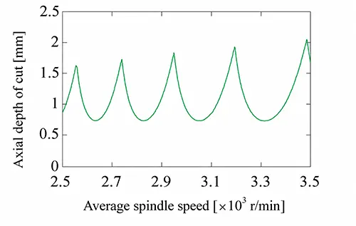
Among the methods used, parameter selection based on stability lobe diagrams is a common approach for flutter-avoidance optimization;
An example of a stability lobe diagram is shown in Figure 1.
For example, BUDAK E and TEKELI A proposed a method to determine the optimal cutting depth parameter combination for chatter-free machining.
The method relies on stability lobe diagrams generated by the zero-order method and achieves the maximization of material removal rate throughout the entire machining process.
TANG A J and LIU Z Q [23] simultaneously considered the effects of spindle speed, axial depth of cut, and radial depth of cut on stability;
They plotted a three-dimensional stability lobe diagram and applied it to guide parameter selection for the machining of thin-walled parts, thereby maximizing the material removal rate.
ZHANG X M and DING H, on the other hand, set the minimization of tool vibration response as their optimization objective.
They extracted data from the stability lobe diagram. They approximated the maximum axial depth of cut under different spindle speeds.
These values were set as nonlinear constraints in the model. Then they adopted the augmented Lagrangian method.
This algorithm calculates the optimal parameter combination. The obtained parameters realize high material removal efficiency under stable cutting conditions.
OZOEGWU C et al. focused on parts with cavity grooves, setting total machining time as the optimization objective.
By optimizing the stable cutting parameters in the stability lobe diagram, they maximized material removal efficiency throughout the entire machining process of the cavity grooves.
Advanced Optimization Algorithms for Stable Cutting Parameters
Furthermore, based on stability results, optimizing stable cutting parameters using efficient optimization methods has become a trend in recent years.
For example, Hu Ruifei et al. developed a parameter optimization model that uses material removal rate and tool life as optimization objectives and milling stability as a constraint.
They introduced expected values of material removal efficiency and tool life into the model.
These values serve as model parameters. This arrangement realizes quantitative balance among multiple optimization objectives.
After that, they adopted a genetic algorithm. The algorithm solves and acquires the optimal milling parameters.
RINGGAARD K et al. employed the penalty function method to establish an optimization function for the MRR of the milling process of thin-walled workpieces;
They took forced vibration and flutter constraints as penalty terms.
The optimization effectively improves machining efficiency and prevents vibration.
Targeting turning operations, KUMAR S and SINGH B first built a parameter optimization model with the response surface method, and then applied a multi-objective genetic algorithm to select machining parameters for maximum MRR in stable cutting regions.
BERGMANN B and REIMER S proposed a self-learning-algorithm-based adaptive optimization method for milling parameters, which prevents chatter by automatic adjustment of machining parameters.
Multi-Objective Parameter Optimization Methods
Parameter optimization not only ensures maximum machining efficiency under flutter stability constraints, but also integrates multiple machining evaluation metrics for comprehensive multi-objective optimization.
For example, DENG C Y et al. constructed a multi-objective optimization model targeting surface positioning error and material removal efficiency.
They combined the non-dominated sorting genetic algorithm, AHP and the Grey Target Decision Method to determine optimal parameters that balance accuracy and efficiency.
AKKUŞ H adopted the Taguchi optimization method and incorporated multiple metrics including surface roughness, energy dissipation, MRR and vibration signals into the model for comprehensive selection of optimal cutting parameters.
Digital Twin and Intelligent Data-Driven Optimization
Gong Chaoguang et al. proposed a multi-objective optimization method based on digital twins.
First, they established a mapping relationship between cutting parameters and machining results using the Gradient Boosting Regression Tree algorithm.
Then, they solved for the Pareto-optimal solution of the milling parameters using a dynamic non-dominant sorting genetic algorithm.
Finally, they adopted two analysis methods. The methods are the Analytic Hierarchy Process (AHP) and the Ideal Solution Similarity Order Preference Method.
They carried out visual ranking through the combination of these methods. In the end, they obtained a set of optimal parameters.
These parameters balance machining efficiency and processing quality.
ZHANG X and other scholars adopted a composite technical scheme.
The scheme integrates online monitoring and offline optimization. They utilize real-time monitoring data.
The data includes cutting force, spindle power and torque signals.
These real-time signals guide the optimization of machining parameters.
Advanced Multi-Objective Optimization for Complex Machining Processes
DENG C Y et al. addressed a multi-stage machining process, setting part surface roughness and cutting time as optimization objectives.
They combined the non-dominant sorting genetic algorithm, the entropy-weighted algorithm, and the best-worst solution distance method to determine the optimal machining parameters and toolpaths.
CHEN X H et al. developed a theory-data coupled model of surface roughness for the milling process of sheet metal workpieces.
They set MRR and surface roughness as optimization objectives, and adopted an improved multi-objective seagull optimization algorithm to optimize multiple machining parameters, including spindle speed, feed rate and cutting depth.
This method achieves comprehensive improvement in both milling quality and machining efficiency of irregular sheet metal parts.
Xi Lin et al. developed a multi-objective optimization model for TC4 titanium alloy milling processes, covering machining efficiency, energy consumption and total bending moment.
They imported experimental results into a radial basis function neural network prediction model and combined it with a particle swarm optimization algorithm for Pareto optimization, finally obtaining an optimal parameter combination that improves multiple metrics.
LU F Y et al. established an energy consumption model and an integrated optimization model considering workpiece deformation constraints for multi-pass machining processes.
They performed hierarchical solving based on a hierarchical reinforcement learning algorithm, with the macro layer handling parameter planning and the micro layer responsible for path generation.
Through interactive feedback and collaboration between the two levels, they optimized cutting parameters and effectively reduced machining time and energy consumption.
Method for Parameter Optimization
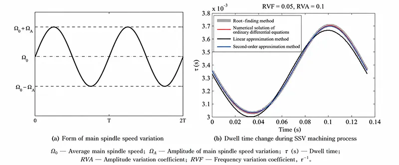
Among flutter suppression methods, spindle speed variation (SSV) technology is an active vibration suppression method that alters the tool lag by continuously varying the spindle speed to counteract the accumulation of flutter, as shown in Figure 2.
Different frequencies and amplitudes of spindle speed variation often result in varying degrees of flutter suppression.
Therefore, optimizing the parameters of the SSV method to enhance flutter suppression performance is a primary focus of many studies on this technique.
Optimization Strategies for SSV Parameters
For example, SEGUY S et al. studied the SSV machining process for triangular variations;
They determined the parameter range for spindle speed variation based on spindle kinematic constraints and used a semi-discrete method to obtain stability analysis results under different SSV parameters, thereby selecting the optimal speed variation parameters to guide the machining process.
ZHU M et al., on the other hand, analyzed the impact of time-delay variations on system energy input during the SSV process from the perspective of energy accumulation.
They proposed an analytical method based on phase delay analysis to optimize SSV parameters and effectively suppress flutter.
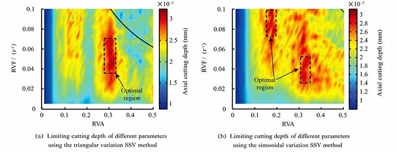
NIU J B et al., based on their self-proposed variable-step-size integration method, conducted stability analyses for both sinusoidal and triangular SSV machining modes, identified optimal parameter regions from the analysis results for parameter acquisition, and presented the parameter optimization results in Figure 3.
> Adaptive Control and Intelligent SSV Optimization
DING L Y et al. conducted a series of studies on the online optimization of SSV parameters in the turning process:
They first established a spindle closed-loop control system based on a proportional-integral-derivative (PID) controller, which can adaptively adjust the amplitude of spindle speed changes when flutter occurs, thereby achieving online flutter suppression;
Subsequently, the controller was optimized into a fractional-order proportional integral differential (FOPID) controller, enabling simultaneous regulation of two parameters: the amplitude and frequency of spindle speed changes.
Building on this foundation, the system’s time-varying dynamic characteristics were incorporated, leading to the proposal of a model-free adaptive sliding mode control algorithm that effectively enhances chatter suppression performance under various environmental and machining conditions.
WANG C X et al. utilized a genetic algorithm to optimize both the spindle speed variation parameters and the tool helix angle during the SSV process, and applied this to high-speed milling to increase the maximum stable axial cutting depth.
> SSV Optimization for Machining Efficiency
NAM S et al. optimized the spindle speed variation profile during SSV application.
Addressing the issue of poor chatter suppression when the spindle speed change rate is low, they independently designed a spindle speed variation profile with constant percentage acceleration to ensure that the spindle speed change rate is maintained at as high a level as possible, thereby enhancing chatter suppression.
The research team further incorporated the workpiece path length and tool radial depth of cut during the SSV machining process into the practical optimization framework.
Using path length as the optimization objective, they achieved a significant reduction in the machining path by selecting optimal machining parameters and SSV parameters.
General Framework for Parameter Optimization
The main process of the aforementioned parameter optimization method consists of three steps:
Constructing a parameter optimization model, establishing a mapping relationship between the optimization objective and parameter variables, and determining the optimal parameters.
The standard parameter optimization process can be summarized as follows:
For different machining processes, specific optimization objectives are selected and combined with corresponding parameter variables and constraints to obtain the optimal parameters.
The variable parameters primarily include cutting depth, spindle speed, and feed rate;
The objective function must be defined based on the actual requirements of the workpiece being machined and production cost considerations.
It can be further categorized into single-objective or multi-objective optimization models, with objective function metrics including material removal efficiency, surface roughness, and vibration signal intensity;
Compliance with constraints (such as flutter constraints) is primarily achieved through two common methods: converting them into penalty function terms or defining the feasible region for parameters.
Trajectory Optimization Methods
For the machining of complex curved parts, the isoparametric or isoplane methods are often used to generate machining trajectories to ensure the smoothness of the machined surface.
However, the machining trajectories obtained using these methods often contain overlapping or congested areas, resulting in extremely low material removal efficiency in those regions and negatively impacting overall machining efficiency.
To address the issue of prolonged machining times, trajectory planning typically requires the integration of tool orientation optimization.
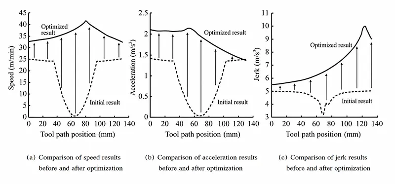
In such methods, with overall material removal efficiency as the objective and the tool’s orientation along the machining path as the optimization variable, the core challenge in enhancing actual machining efficiency through path optimization technology is to increase the maximum allowable feed rate or shorten the overall length of the tool path while satisfying constraints such as flutter, drive-axis motion capabilities, and the tool’s material removal capacity.
Methods for Optimizing Motion Parameters
Increasing the maximum allowable tool speed is primarily achieved by adjusting the trajectory position to expand the range of constraints imposed by the machine tool’s drive axes on the tool’s feed motion in critical areas, or by smoothing corners to reduce the maximum curvature of the trajectory, thereby expanding the range of curvature constraints that the tool’s feed speed must satisfy at corners, ultimately ensuring that the tool can achieve higher feed speeds.
Regarding trajectory optimization under drive-axis constraints, LAVERNHE S et al. developed a tool path surface model incorporating both machine kinematic and geometric constraints for high-speed milling on five-axis machines.
By identifying an optimal tool axis orientation, they maximized the tool’s motion parameters, thereby effectively reducing machining time.
Their tool path optimization method is shown in Figure 4.
YE T et al. first established a mapping relationship between the tool tip motion and the drive axis motion.
They then constructed a trajectory optimization model with material removal efficiency as the objective and formulated it as a concave quadratic programming problem to obtain the optimal machining trajectory.
Corner Smoothing Techniques for High-Speed Machining
Regarding corner smoothing, SHAO W et al. proposed a G2 continuous path optimization method based on a spiral curve for corner machining paths in five-axis side milling processes.
They optimized the path by setting the minimization of tool speed variations and the maintenance of constant cutting force as optimization objectives, thereby obtaining machining paths that ensure the tool remains in high-speed motion and reduce machining time.
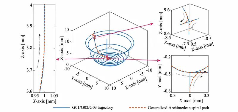
Our research team, however, proposed a corner smoothing method based on the Euler spiral, as shown in Figure 5.
This method achieves spatial corner smoothing for machining paths that combine G01, G02, and G03 commands during CNC machining, effectively increasing the feed rate of machining paths involving different G-codes in three-axis machining.
B-Spline Trajectory Smoothing Methods
Regarding B-spline trajectory smoothing, MERCY T et al. proposed a parallel trajectory optimization method.
This method not only plans time-optimal machining trajectories while considering machine motion constraints and workpiece contour error constraints but also performs optimization calculations for multiple spline segments simultaneously, thereby improving the computational efficiency of trajectory optimization.
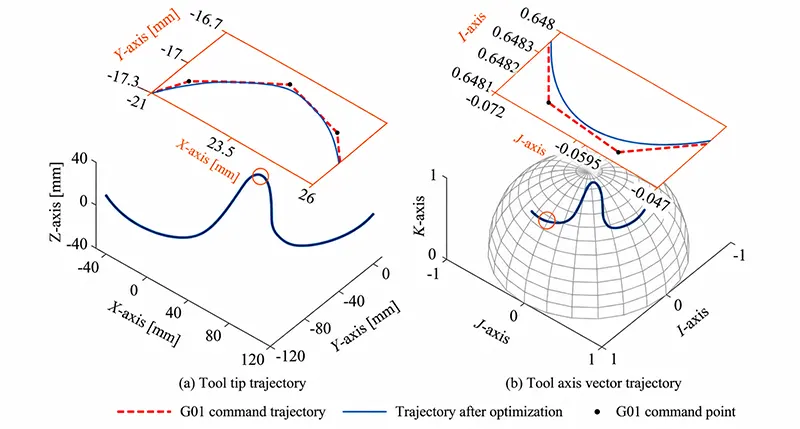
Our research team has proposed a local B-spline three-axis trajectory corner smoothing method and a multi-corner joint smoothing method for B-spline five-axis trajectories.
These methods have achieved increased tool speeds at corners for three-axis G01 trajectories and five-axis short straight-line segments, respectively.
The B-spline smoothing method for five-axis trajectories is shown in Figure 6.
Methods for Optimizing Path Length
With regard to path length, the goal is to reduce the overall path length by optimizing the cutting width or feed direction of the tool path, subject to constraints on residual height and tool load.
For example, HU P C et al. proposed a five-axis toolpath optimization algorithm based on the isoplanar method, with overall material removal efficiency as the optimization objective.
This algorithm comprehensively considers the machine tool’s motion capability constraints and the maximum residual height constraint of the toolpath to obtain the optimal tool tip path, and then adjusts the tool axis vectors with material removal efficiency as the objective, ultimately improving the efficiency of the five-axis toolpath.
The toolpath optimization method for path length is shown in Figure 7.
Geodesic and Mathematical Optimization Approaches
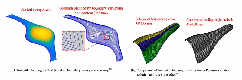
LIANG F et al. proposed a toolpath planning method for non-uniform rational B-splines ( NURBS) surfaces.
This method constructs a shortest boundary geodesic map in the NURBS parameter space and maps it to a closed 3D toolpath.
It then determines the spacing between adjacent paths based on the cutting depth constraint, ultimately achieving a significant reduction in toolpath length.
The toolpath planning method based on the boundary geodesic map is shown in Figure 7(a).
ZOU Q proposed an implicit toolpath planning method based on the Poisson equation for the machining of parametric and mesh surfaces.
This method reduces the problem of optimizing toolpath length to a balanced optimization problem between the tool feed direction and the residual height along the trajectory.
By using the energy minimization method, this problem is transformed into solving the Poisson equation, ultimately yielding toolpaths that effectively shorten the overall length.
The comparison results are shown in Figure 7(b).
Intelligent Toolpath Planning and Optimization Algorithms
YUAN C M et al. used a differential graph algorithm to sequentially generate the tool axis vector direction at any position on the surface and the corresponding tool tip trajectory position.
While ensuring compliance with the residual height constraint, they maximized the cutting width of the tool tip trajectory, thereby achieving a significant reduction in trajectory length.
JACSO A et al. proposed a B-spline-based trajectory generation algorithm for cycloidal milling processes.
Under the constraint of tool load limits, they used a differential evolution algorithm to optimize the control points of the B-spline, thereby maximizing the overall material removal efficiency of the tool path.
ZHANG C Q et al. proposed a global toolpath planning method based on the vector field method.
This method does not require prior division of surface regions, effectively improves surface continuity at the edges of adjacent regions, and can comprehensively consider the overall path length, the variance in residual height of adjacent paths, and toolpath continuity to generate an optimal machining path.
PUNUGUPATI G et al. proposed a voxel-model-based zigzag rough milling toolpath planning method.
Aiming to shorten cutting path length, reduce idle cutting paths, and minimize corner turning angles, the method optimizes the toolpath by combining the non-dominant sorting algorithm with a genetic algorithm, ultimately achieving a reduction in path length.