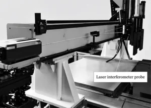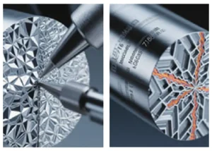
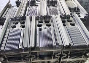
Common challenges encountered during the machining of parts include numerous machining features, high requirements for geometric accuracy, and thin-walled areas that are highly prone to deformation.
Addressing these machining challenges has been a focal point of research for many scholars.
Relevant researchers have analyzed the structures of shell parts and conducted research on machining technologies based on clamping methods, machining processes, and toolpaths tailored to specific features. Additionally,
some researchers have analyzed the structures of air rudder parts and their corresponding processes, studying CNC machining technologies through machining processes and specialized fixtures.
By analyzing the characteristics of thin-walled aircraft support parts and designing customized specialized fixtures, we optimize the machining process plan, reduce machining errors, and improve the surface quality of workpieces.
Current CNC machining workflows for thin-walled parts adopt the following procedures:
In the process design stage, researchers primarily apply finite element analysis (FEA) to identify deformation zones and correct these zones via CNC compensation technology, thereby improving machining accuracy.
Researchers optimize cutting parameters to minimize deformation along machining paths and develop specialized cutting tools and modified machine tools to mitigate deformation issues.
Analysis of Factors Affecting the Machining of Thin-Walled Parts
There are numerous factors that influence the machining of thin-walled parts, such as the material and structural configuration of the part, as well as factors like cutting heat and surface hardening.
Influence of Material and Structural Configuration
Different materials have varying machinability characteristics. During the machining process, the cutting forces and cutting heat generated differ, and consequently, their impact on the workpiece’s dimensional change parameters also varies;
Even for identical materials, structural differences in thin-walled parts, such as varying rib configurations, lead to distinct dimensional variations under consistent machining processes.
Aluminum alloys see extensive application in the aerospace industry, featuring a low elastic modulus and a high yield-to-tensile strength ratio.
They are highly susceptible to springback deformation during machining. In addition, they tend to undergo plastic deformation easily in the machining process.
Furthermore, since parts of this type are typically thin-walled, the machining difficulty is increased.
Influence of Cutting Force Factors
During the cutting process, it is necessary to ensure a stable metal removal rate to maintain constant cutting load.
In research based on mechanical models, the average milling force model is frequently used.
In combination with specific machining models, experiments are conducted across multiple sets of cutting parameters to measure the three-dimensional average force on thin-walled parts.
Researchers set the values of undetermined constants to derive a mathematical model for cutting forces in thin-walled part machining.
However, in actual machining, cutting forces undergo dynamic changes, and the magnitude of these fluctuations has a particularly pronounced effect on the deformation of thin-walled parts.
Since the machining of thin-walled parts occurs in an intermittent state, the following factors influence changes in cutting forces:
First, the cutting volume undergoes periodic changes as the cutting tool penetrates the workpiece; the frequency of these changes varies in integer multiples of the tooth pitch.
Cutting parameters determine the cutting force; reducing the depth of cut decreases the degree of deformation;
Additionally, systemic vibrations occur during the cutting process.
When feed rates are increased during machining, the machine tool’s natural frequency must meet specific requirements.
Under high-speed machining conditions, the variations in cutting forces caused by flutter are higher than the average milling force;
Therefore, measures must be taken to prevent flutter near the system’s natural frequency.
Clamping Factors
These factors ensure proper positioning of the workpiece on the machine tool and maintain its stability under external loads.
For the machining of thin-walled parts, clamping can cause some degree of workpiece deformation.
While this clamping-induced deformation is difficult to eliminate, optimizing the clamping method can mitigate it.
Operators can select diverse clamping methods, sequences, and positions to effectively control workpiece deformation.
During the milling process, the clamping forces generated by the clamping method and the cutting forces continuously act on the workpiece, redistributing the part’s initial residual forces and residual stresses generated during machining, thereby causing workpiece deformation.
For parts with significant springback deformation, clamping-induced deformation is even more severe.
When operators clamp a workpiece with a three-jaw self-centering chuck, they mainly apply forces at three points. This uneven force distribution readily induces clamping deformation.
A slotted sleeve applies clamping force uniformly around the workpiece during clamping, which reduces clamping errors and effectively improves machining accuracy.
Influence of Machining Path Factors
For the same workpiece, the machining path may vary, as may the number of clamping operations and product quality.
This is primarily due to differences in machining paths, which result in variations in precision assurance and machining time during the process.
In addition to the factors mentioned above, cutting parameters, tool dimensions, and machining processes all affect the machining accuracy and efficiency of the workpiece.
Part Structural Composition
The main structural features of heat sink components include the following:
Through holes, sector-shaped cavities, circular cavities, rectangular cavities, flat surfaces, hemispherical surfaces, curved surfaces, fillets, flow channels, and U-shaped grooves.
Machining features are present on both the front and back surfaces of the part.
The structure is relatively complex, requiring high positional accuracy.
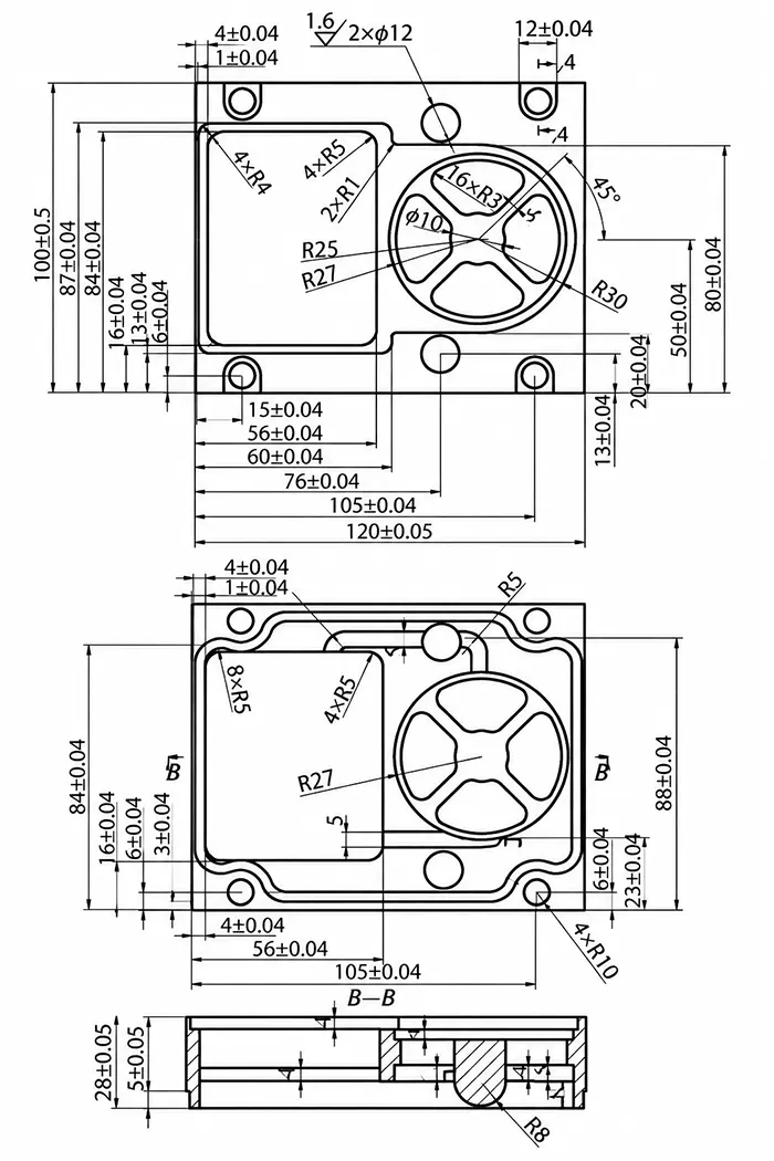
The defined contour dimensions are 120 mm × 100 mm × 28 mm, and the material is aluminum alloy.
We adopt the following machining specifications: Unless otherwise specified, all dimensions follow IT13 tolerance grade.
The part contains four through-holes, with one measuring 8 mm and two measuring 12 mm. See Figure 1 for specific dimensional specifications.
Machining Process Analysis
Challenges
First, positional accuracy cannot be guaranteed.
Since the part has machining features on both its front and back surfaces, the conventional method of securing the part to the fixture plate required multiple clamping operations.
This process accumulates positional accuracy errors, causing deviations in the machining positions on the front and back surfaces of the part.
Additionally, the influence of the clamping plates makes it difficult to complete the machining of the entire part in a single operation, thereby reducing the efficiency of mass production.
We therefore design a dedicated positioning fixture. According to the part structural characteristics, we select two appropriate feature holes as clamping and positioning holes to ensure precise workpiece positioning.
Secondly, thin-walled parts are highly prone to deformation during machining.
The wall thickness at the thinnest point of the part is 1 mm, while at the thickest point it is 4 mm. A significant amount of material must be removed during the process.
As material is removed, cutting forces and heat generated during machining can easily cause deformation in the thin-walled areas.
The removal of large amounts of material from the interior of the part reduces its rigidity, and the cutting forces exerted by the tool can also cause deformation in the thin-walled areas, thereby affecting the part’s machining accuracy.
These factors must be taken into account during the design of the specialized fixture to prevent deformation of the part’s thin-walled areas.
Selecting Cutting Tools
Radiator parts require extensive machining operations, including milling, drilling, and reaming, which demand a wide range of cutting tools.
We select carbide cutting tools according to the parts’ material properties.
We further determine optimal cutting tools based on the dimensional characteristics and machining requirements of radiator parts.
See Table 1 for specific cutting tool specifications.
| No. | Tool Name | Tool No. | Diameter (mm) | Length (mm) | Cutting Edge Length (mm) |
|---|---|---|---|---|---|
| 1 | Drill Bit | T01 | 10 | 75 | 35 |
| 2 | Reamer | T02 | 12 | 75 | 35 |
| 3 | End Mill | T03 | 20 | 75 | 45 |
| 4 | End Mill | T04 | 10 | 45 | 45 |
| 5 | Ball End Mill | T05 | 4 | 65 | 20 |
| 6 | Center Drill | T6 | 2.5 | 60 | 20 |
| 7 | Twist Drill | T7 | 8 | 65 | 35 |
Table 1. Tool Card
Planning the Machining Process
We optimize the machining plan for efficiency according to the structural characteristics of the part.
Since both the front and back surfaces of the part require machining, multiple setups are necessary.
Meanwhile, we guarantee the part’s relative positional accuracy to achieve high-precision positioning.
In the first setup, we pre-machine two 12 mm-diameter through holes with a surface roughness of Ra 1.6 μm on the blank to serve as locating holes via a drill-ream-tap process.
In the second setup, we complete the rough machining of regions A, B, D, and the U-shaped groove on the front face, followed by semi-finishing and finishing operations.
These surfaces will serve as the reference plane for the third setup.
In this clamping state, we perform rough, semi-finish, and finish machining on all reverse-side regions, alongside machining four 8 mm holes.
We define the workpiece blank dimensions as 130 mm × 110 mm × 30 mm.
Design of a Specialized Fixture
1. Design Requirements and Design Objectives of the Dedicated Fixture
This part is produced in batches.
Previously, the clamping method using a fixture plate was inconvenient, made it difficult to address thin-wall deformation issues, and made it hard to ensure the part’s positional accuracy.
By analyzing the machining process and designing a dedicated fixture, we address key process requirements: convenient clamping operation and guaranteed part positional accuracy.
And ensuring that the part does not deform after clamping or, if deformation occurs, that it does not affect machining accuracy.
We design the fixture clamping force to counteract milling forces, minimize thin-wall deformation effects, and ensure the workpiece dimensional tolerances meet operational requirements.
2. Locating Scheme and Multi-step Clamping Strategy
We employ two locating pins because the part requires machining on both front and back surfaces. In the first clamping operation, we machine a 12 mm-diameter locating hole.
This hole lies below the reverse-side machining surface and doubles as a clamping structure to guarantee sufficient structural strength.
For the second and third clamping operations, we adopt a single-sided two-pin positioning method to satisfy positional accuracy requirements.
The fixture clamping force mainly derives from the lead screw driving the clamping plate and pin columns.
The clamping plate possesses two major functional advantages in practical machining.
First, it provides stable clamping force. This structure enables the lead screw force to be uniformly distributed on the contour surface of the workpiece.
It effectively avoids workpiece deformation induced by local stress concentration.
Second, the clamping plate restrains surface deformation of thin-walled structures.
This protective effect works during the milling process of specific regional features.
During the fourth clamping operation—which involves roughing, semi-finishing, and finishing of the part’s outer contour—the part is not secured via leadscrews or clamping plates but is primarily held in place by pins.
Since the internal machining of the part is complete and the part is hollow, its rigidity is reduced.
Because thin-walled sections are highly prone to deformation during external contour machining, the design incorporates a mating relationship between the boss and the internal contour on the opposite side to enhance the part’s rigidity.
3. Finite Element Simulation Setup and Milling Force Calculation Formula
This study aims to facilitate subsequent machining simulation of the workpiece.
It is essential to clarify the influence of milling forces on workpiece deformation under various clamping conditions.
Two clamping modes are compared in this research, namely the traditional fixture plate and the dedicated special fixture.
Assuming consistent milling forces, finite element software is used to analyze the specific deformation values of thin-walled sections under different clamping conditions.
The specific formula for calculating milling force is as follows:

In the formula, C is the material milling condition coefficient, v is the milling speed, d is the tool diameter, f is the feed rate, aw is the milling width, and ap is the milling depth.
Simulated Machining Process for Parts
Machining Simulation Process and Risk Detection
First, create a new project, define the machining station, and select the control system and CNC machining center corresponding to the laboratory’s equipment.
Import the fixture, workpiece blank, and part design model in sequence.
After completing these steps, conduct a simulated machining test on the part to evaluate the results.
This process allows for the detection of issues such as overcutting, material residue, and collisions during the machining stage, enabling technicians to make timely corrections.
Accuracy Verification and Deformation Suppression Effect Evaluation
Verifying Part Accuracy: Use advanced automation features to verify part accuracy.
After completing the simulation, compare and analyze the machined part against the design model.
Over-machined areas are marked in light gray with a tolerance of 0.04 mm, while under-machined areas are marked in dark gray with a tolerance of 0.04 mm.
If no colors appear, it indicates there are no over-machined or under-machined areas, meaning the part meets the accuracy requirements.
During the machining process, a single-face, two-pin positioning method effectively improves part positioning accuracy.
The third clamping stage, the fixture’s clamping plate suppresses outward deformation of the thin-walled sections.
During the fourth clamping stage, the fixture’s boss suppresses inward deformation of the thin-walled sections.
Both of these factors influence machining accuracy.
Batch Production Efficiency and Economic Benefit Analysis
Based on dimensional accuracy measurement data, the part meets machining accuracy requirements, demonstrating that this approach effectively suppresses thin-walled deformation and improves machining accuracy.
The workpiece is produced in batches and requires repeated clamping operations.
Traditional fixture plates suffer from several practical limitations in this scenario.
They reduce the overall positioning accuracy and cause inconvenient workpiece loading and unloading.
This process leads to substantial waste of time and labor costs. Meanwhile, the total machining cycle time is correspondingly prolonged.
With the specialized fixture, parts can be loaded and unloaded simply by adjusting the fixture lead screw, thereby reducing both time and labor costs.
At the same time, the fixture’s locating pins ensure the positional accuracy of the part during clamping.
Batch production of this part shortens the production cycle and increases economic benefits.
Conclusion
By conducting a comprehensive analysis of parts and developing more rational machining plans, we ensure that specialized fixtures are designed with higher positioning accuracy and ease of clamping, effectively minimizing deformation.
This approach significantly improves machining accuracy and efficiency.
Utilizing simulation software to conduct virtual machining tests on parts ensures the rationality of the machining process, resolves issues that may arise during machining, and guarantees a more rational machining process.
The innovative aspect of this study lies in the combination of physical and geometric simulation to avoid the limitations of previous research that relied solely on a single type of simulation.
This approach simplifies the design of specialized fixtures, effectively suppresses deformation, and achieves high positioning accuracy.
Deriving the formula for the maximum cutting volume in the CNC machining of thin-walled parts requires a foundation in the principles of materials mechanics and the establishment of a stress model for the part, which is used to determine the limit load values and ensure machining quality.
Regarding elastic deformation, once the cutting force conditions are determined, the maximum cutting volume for thin-walled parts can be calculated to meet machining accuracy requirements, enabling the parts to be machined to the final desired dimensions.
In CNC machining of thin-walled parts, it is essential to ensure precision, effectively remove excess material, and improve machining efficiency.