Trajectory Optimization Methods Under Flutter Constraints
During five-axis machining of curved-surface parts, cutting parameters often vary depending on the position of the surface.
Relying solely on parameter optimization methods to prevent or suppress chatter makes it difficult to address the complex variations in surface trajectories.
Therefore, existing surface trajectory optimization methods typically incorporate chatter stability constraints into the planning process and plan optimal trajectories based on the specific conditions of the surface’s position.
Chatter-Free Toolpath Optimization Through Tool Axis Adjustment
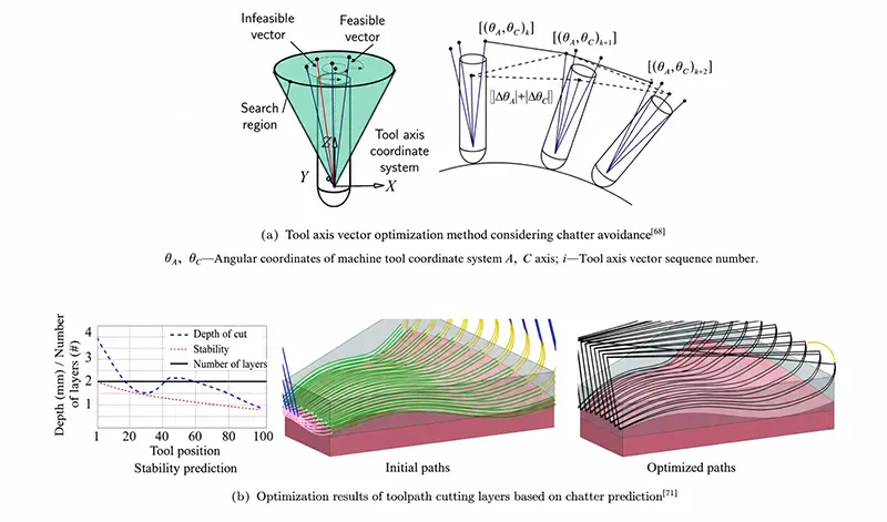
For example, SUN C and ALTINTAS Y proposed a method for avoiding chatter during five-axis machining with ball-end mills by automatically adjusting the tool axis vector of the trajectory.
This method first constructs the dynamic characteristic equation in the tool-workpiece contact coordinate system, applies the Nyquist stability criterion to each tool position to search for chatter-free tool axis directions, and then identifies the optimal tool axis vector direction among them.
As shown in Figure 8(a), this approach achieves both flutter avoidance and length optimization for toolpaths on complex surfaces. TANG X W et al. proposed a stability prediction method that accounts for changes in tool orientation during the five-axis machining process using a bullnose end mill.
Through coordinate transformations and vector projections, they precisely identified the tool-workpiece contact area and established a dynamic cutting force model.
Finally, with the goal of maximizing material removal efficiency, they improved machining efficiency by optimizing the tool axis direction within the stability domain.
Multi-Constraint Trajectory Optimization Strategies
HUANG T et al. established a corresponding maximum-minimum optimization model based on flutter stability constraints and surface position error constraints, intending to minimize changes in tool direction between adjacent tool positions.
They solved for the optimal trajectory positions using a sequential linear programming method to obtain prediction results for flutter and surface position errors, which were used to guide the subsequent trajectory optimization process.
TUNC L T set material removal efficiency as the optimization objective, comprehensively considering multiple constraints such as flutter stability and residual height.
By optimizing cutting parameters to reduce the number of cutting layers in the tool path, as shown in Figure 8 (c), a significant reduction in path length was achieved.
KARIMI B and ALTINTAS Y proposed a variable-cutting-rate path planning method for the milling of thin-walled blades, whose core idea is to plan smaller cutting parameters in the flexible regions of the workpiece to impart higher local stiffness, thereby effectively preventing flutter and reducing workpiece deformation errors.
Building on this, to minimize total machining time, a genetic algorithm is used to determine the optimal path lengths and tool cutting thicknesses for different workpiece regions, ultimately achieving improved machining efficiency while ensuring blade surface quality.
Advantages and Challenges of Trajectory Optimization
The trajectory optimization methods described above primarily improve overall cutting parameters or increase the allowable speed by adjusting the tool tip position or the tool axis vector.
This avoids extreme regions along the trajectory—such as areas with extremely low cutting depths or maximum allowable speeds, or regions prone to chattering—thereby enhancing overall material removal efficiency during the machining process.
Compared to parameter optimization techniques, path optimization has a broader scope of optimization objectives and can fully incorporate the actual conditions of the workpiece’s cutting area to achieve better performance improvements;
However, path optimization also involves more complex constraints, presenting greater difficulty and challenges.
Speed Planning Methods
The task of speed planning is to continuously plan the tool feed rate under trajectory speed constraints, ultimately generating position commands at each sampling time for actual machining.
Compared to trajectory optimization and parameter optimization, the core challenge of speed planning lies in achieving efficient feed rates while ensuring real-time interpolation calculations.
Additionally, speed planning for five-axis trajectories must also take into account the motion constraints of the drive axes.
In recent years, numerous researchers have conducted extensive studies on speed planning methods, focusing on areas such as machining efficiency, computational efficiency, and motion constraints.
Speed Planning Methods Based on Efficiency Metrics
Increasing feed rate is one of the primary objectives of speed planning.
To effectively achieve this, many researchers use metrics such as material removal efficiency, cutting force, and machining time as references during the planning process, and plan and arrange speeds appropriately based on changes in these metrics.
Feed Rate Optimization Based on Cutting Force Prediction
For example, ERDIM H et al. used cutting force as a constant parameter in speed planning, optimizing the feed rate of the current trajectory to maximize the tool’s material removal capacity and reduce machining time.
SALAMI R et al. first developed a cutting force prediction model for ball-end mills during three-axis milling operations and optimized the feed rate based on the model’s predictions, thereby achieving feed rate optimization under the constraint of maximum cutting force.
BEUDAERT X et al. used the machine tool’s motion capabilities as constraints during speed planning; they employed an iterative algorithm to obtain feed motion curves with minimum processing time and implemented the interpolation of linear and NURBS trajectories on the machine tool.
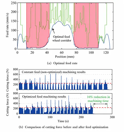
ERKORKMAZ K et al. used the variation in cutting forces of the ball-nose end mill during the milling process as a guide.
While ensuring compliance with cutting force and kinematic constraints, they constructed a continuous acceleration-deceleration feed motion curve based on a continuous feed profile with increasing acceleration.
The planning results are shown in Figure 9; compared with conventional constant-feed methods, this approach effectively reduced machining time.
PARK H S et al. integrated cutting force prediction capabilities with intelligent algorithms.
In an automated machining system, they set cutting force maximization as the optimization objective and automatically adjusted the current feed rate based on cutting force prediction results, thereby achieving feed rate optimization.
Multi-Objective Feed Rate Optimization
HAN Y J et al. developed an optimization model based on the Gaussian mixture model method, incorporating various metrics such as feed rate, cutting depth, material removal volume, and path spacing.
While ensuring compliance with machine tool performance constraints, they achieved the optimization and adjustment of the feed rate.
VAVRUSKA P et al. incorporated spindle kinematic constraints and the influence of tool cutting depth when planning spindle speed and feed rate.
Through the joint optimization of these two parameters, they simultaneously achieved effective improvements in both machining efficiency and tool life.
Real-Time Speed Planning Algorithms
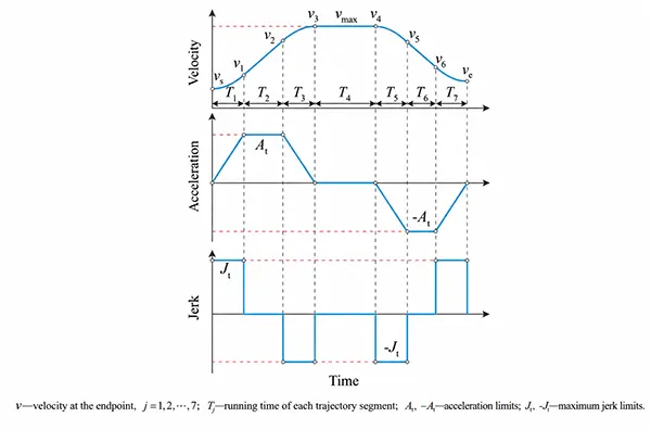
In terms of computational efficiency, speed planning methods can achieve efficient interpolation of tangential feed rates by deriving analytical expressions for feed profiles (e.g., the S-shaped speed planning method shown in Figure 10) or by using spline interpolation.
Analytical Feed Profiles and Spline Interpolation
For example, ERKORKMAZ K and ALTINTAS Y developed feed profile curves with limited double acceleration and continuous acceleration for spline tool paths to enable real-time calculation of feed rates.
ERKORKMAZ K subsequently proposed an analytical expression for feed contour curves with continuous double acceleration, achieving third-order continuity in tool motion.
Experimental verification against second-order continuous tool feed machining demonstrated that third-order continuous tool feed motion offers higher tracking accuracy and a lower acceleration frequency.
LIN M T et al. developed an interpolator for NURBS trajectories capable of rapidly calculating spline curvature, effectively ensuring compliance with curvature constraints during real-time interpolation.
DU D et al. incorporated additional constraints on acceleration and deceleration into the NURBS interpolation process and, addressing issues such as high curvature and abrupt changes in acceleration and deceleration along curved trajectories, proposed a real-time flexible acceleration and deceleration method that reduces the vibration and shock experienced by the drive shaft during curved motion.
Real-Time Interpolation and Computational Optimization
ZHAO H et al. proposed a real-time speed planning algorithm based on B-spline smooth trajectories for short straight-line segments.
This algorithm, based on a bidirectional scanning method, ensures that the planned feed rate satisfies the continuity and double-acceleration constraints, and achieves real-time machining of complex three-axis parts using parametric and linear interpolation methods for spline arc lengths.
DU X et al. first divided the NURBS spline trajectory into different speed planning intervals based on the points of maximum curvature.
They summarized the S-shaped speed planning method for acceleration and deceleration scenarios corresponding to different interval lengths and performed optimal speed planning.
Subsequently, they used the bidirectional scanning method to adjust the speed, ensuring speed continuity at the connection points between different intervals;
Finally, they employed a Taylor series expansion to rapidly compute the interpolation points along the NURBS trajectory.
ERKORKMAZ K et al. proposed a fast interpolation algorithm combining linear interpolation with a parallel window algorithm.
For interpolation operations involving longer trajectories, this algorithm can reasonably select trajectory connection points within parallel windows based on optimization principles to perform parallel calculations for trajectory interpolation, thereby achieving efficient toolpath interpolation while ensuring computational accuracy.
Five-Axis Trajectory Speed Planning Algorithm
In the actual planning process, the speeds of the drive axes for a three-axis trajectory do not exceed the tangential speed of the tool;
Therefore, during planning, it is possible to quickly determine whether the axial constraints are met based on the tangential speed of the tool trajectory.
In contrast to three-axis trajectories, due to the presence of rotational motion, the smoothed five-axis spline trajectory must be divided into a tool tip trajectory and a tool shaft trajectory to represent the motion of the tool tip and the tool shaft, respectively.
In this case, there is no longer a linear relationship between the tool’s motion relative to the workpiece and the motion of the drive axes, necessitating specific consideration of the motion constraints for five-axis trajectories.
Conventional speed planning for smoothed spline trajectories typically involves planning the tool tip trajectory, with the tool axis trajectory’s interpolation points derived directly from the correspondence with the tool tip trajectory.
This method leads to a situation where, during actual speed planning, there is no direct analytical relationship between the positions of the interpolation points and the spline arc length.
Consequently, when handling drive axis over-limit conditions caused by changes in the tool axis vector, iterative adjustments are required, making it difficult to perform effective adjustments and optimizations directly based on the current speed.
Feed Rate Planning Under Drive-Axis Motion Constraints
To address the issue of drive axis motion constraints exceeding limits in tangential velocity planning for five-axis toolpaths, SENCER B et al. proposed a feed rate optimization strategy based on B-splines that ensures continuous acceleration.
This strategy adjusts the feed rate while iteratively refining the control points of the B-spline, thereby optimizing the feed rate while ensuring that the drive axis remains within its motion constraints.
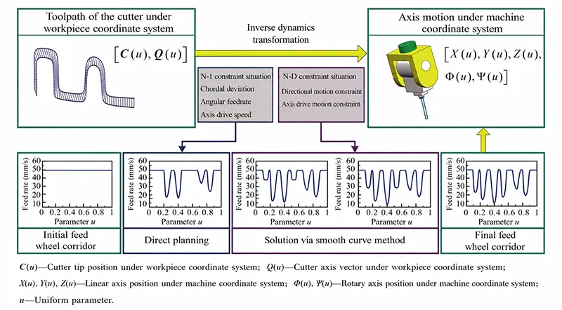
SUN Y W et al., based on the characteristics of the tool path, classified the paths in the out-of-bounds region into constraint-independent and constraint-dependent regions according to whether their own constraints were affected by the motion constraints of adjacent paths.
In constraint-independent regions, the feed profile curve can be adjusted directly, while in constraint-dependent regions, adjustments are made through iterative calculations combined with decoupling operations to reduce dependence on constraints, bringing the portions exceeding the limits back within the feasible constraint domain, thereby achieving effective feed planning for five-axis trajectories, as shown in Figure 11.
> Drive-Axis Constraint Transformation and Efficient Feed Rate Calculation
LU L et al. transfer the motion constraints of the drive axes in the machine coordinate system to the workpiece coordinate system—where the tool path resides—as much as possible, and then use the bang-bang control principle to determine the feed rate profile.
Although the above method can ensure compliance with the kinematic constraints of the five-axis trajectory, it still requires iterative calculations to find the optimal feed motion while satisfying the kinematic constraints of the drive axes, making it difficult to meet the requirements of real-time interpolation in practical applications.
To further improve computational efficiency, SUN Y W et al. used a scaling method to transform the nonlinear constraint problem posed by the drive-axis motion constraints on feed motion into a linear constraint problem, thereby enabling rapid feed rate calculation.
> Constraint-Sensitive Region-Based Feed Planning Strategies
MA J W et al. divided the trajectory into constraint-sensitive regions (prone to exceeding limits) and non-sensitive regions (less prone to exceeding limits) based on trajectory characteristics and drive-axis motion constraints.
They planned conservative, low-speed, constant-feed motion in the constraint-sensitive regions and arranged accelerated motion in the non-sensitive regions to improve tool feed efficiency;
This method effectively achieved rapid planning and interpolation of tool tangential motion.
However, both of the above methods amplify the feed constraints to some extent, and there is still room for further optimization of the planned feed rates.
> Analytical Feed Rate Planning Based on PH Splines
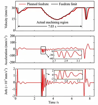
The authors’ team, based on the arc-length parameterization property of Pythagorean-hodograph (PH) splines, implemented analytical calculations for both drive-axis motion and tangential motion, thereby enabling analytical adjustment of tool feed based on drive-axis motion constraints.
Building on this, to maximize material removal efficiency, they planned feed rates using a motion profile with continuous acceleration and deceleration, as shown in Figure 12, thereby improving machining efficiency.
Motion Blending Methods for Five-Axis Trajectories
The methods described above primarily address tangential motion planning for spline trajectories.
In addition, the single-axis motion blending method is another speed planning method capable of achieving efficient computation while ensuring constraints on the drive axes for five-axis trajectories.
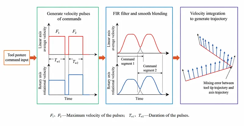
This method directly plans the corresponding feed motion in the machine tool coordinate system based on the drive axis constraints and path length;
It then blends and superimposes the motion results of adjacent trajectory plans to achieve continuous tool motion planning;
Finally, by integrating the planned tool motion, the interpolation points for a smooth trajectory are obtained, as shown in Figure 13.
> FIR Filter-Based Feed Motion Planning and Trajectory Smoothing
Compared to tangential velocity planning methods, this approach avoids the complex arc length calculations involved in spline smoothing methods.
It is an efficient trajectory interpolation method that integrates corner smoothing and velocity interpolation, offering significant advantages in computational efficiency and real-time interpolation.
For example, TAJIMA S et al. and TAJIMA S et al. utilized finite impulse response (FIR) filters to plan feed motions with limited acceleration based on the kinematic constraints of each machine tool drive axis.
They also derived a constraint relationship between the trajectory superposition length and the error at corners, and under the guidance of this constraint, achieved five-axis trajectory smoothing and velocity planning interpolation that satisfied the error limits.
Our team adopted a method combining FIR filters and motion blending to plan the tool’s translational and rotational motions in both the workpiece coordinate system and the machine tool coordinate system, respectively.
Based on the maximum axial and tangential kinematic constraints of each axis, we proposed a method for predicting and correcting constraint errors, thereby minimizing machining time while ensuring compliance with the constraints.
> Advanced Feed Rate Blending and Interpolation Strategies
LIN M T et al. first planned the feed rates for individual linear segments of a five-axis trajectory while ensuring compliance with drive-axis constraints.
They then combined the bidirectional scanning method with a velocity blending method to ensure that adjacent linear segments generated smooth, continuous feed rates and toolpaths, thereby achieving real-time online interpolation of the five-axis trajectory.
SONG D N et al. combined the FIR filter method with the spline smoothing method.
They first generated linear feed rates based on the curvature of the smoothed spline trajectory and the given kinematic constraints, then applied two cascaded FIR filters to the initially generated feed rates to obtain feed rate planning results that satisfy the constraints and possess higher-order continuity, ultimately achieving efficient trajectory smoothing and interpolation calculations.
> Optimization of Machining Efficiency and Contour Accuracy
TANG P Y et al. established an analytical relationship between feed rate at corners and contour error based on a dual-FIR filter strategy, thereby achieving dual improvements in machining efficiency and contour accuracy during tool motion planning.
HUA L et al. performed coordinated motion planning for multiple machine tool axes based on the S-curve speed planning method;
This approach significantly reduced the computation time for smoothing trajectory interpolation while ensuring machining accuracy and compliance with kinematic constraints.
Key Characteristics of Five-Axis Speed Planning Methods
Speed planning methods for milling operations primarily aim to maximize speed.
Different methods take into account factors such as high-order continuity, real-time interpolation calculations, cutting forces, and constraints on the motion capabilities of the drive axes.
Among these, speed-enhancement methods break through the limitations of conventional constant maximum feed rates by adjusting the current feed rate based on changes in additional metrics (such as cutting forces and material removal efficiency);
High-order continuity methods, on the other hand, additionally seek continuity in acceleration and jerk to reduce the frequency of acceleration and vibration impacts during tool motion.
These methods typically feature analytical expressions for speed, thereby offering the advantage of high computational efficiency.
For speed planning of five-axis trajectories, the rotational motion of the tool introduces nonlinear transformations between coordinate systems, significantly increasing the complexity of ensuring compliance with drive-axis motion constraints.
Summary and Outlook
In the five-axis milling process, parameter optimization, trajectory optimization, and speed planning are three effective methods for ensuring efficient tool operation.
Among these, parameter optimization—based on tool capabilities, workpiece requirements, and machine tool environment—serves as the preliminary process and foundation for the implementation of the other two technical methods;
Trajectory optimization, on the other hand, performs a secondary optimization of the tool’s position and axis orientation based on the initial trajectory generated from the optimal parameters, while taking into account the actual cutting area of the workpiece.
Combining the results of trajectory optimization with the optimal parameters determines the actual length of the final trajectory;
Simultaneously, the trajectory shape dictates the maximum allowable speed at different positions, thereby providing specific motion constraints for subsequent speed planning.
Finally, based on these motion constraints, speed planning technology is used to determine the feed rate of the cutting tool at any given position and to generate interpolation commands that guide the tool’s actual motion.
To date, significant progress has been made in the research methods for these three technical approaches; however, they still fall short of meeting the demands for efficient production of existing components, and further research is needed to address the following issues.
(1) Improving the Computational Efficiency of Parameter Optimization
Parameter optimization methods that account for the effects of flutter rely on stability analysis to select optimal parameters.
Due to the computational methods inherent in stability analysis, obtaining optimal parameters requires a large number of iterative calculations.
Further research is needed to improve the computational efficiency of parameter optimization and to transform it from an exhaustive search into an analytical solution to an optimization problem;
(2) Advancing Time-Optimized Trajectory Planning
Current five-axis trajectory optimization methods struggle to unify speed optimization with trajectory length optimization and are, to some extent, constrained by the shape of the initially generated trajectory.
Generating time-optimized five-axis trajectories—rather than those optimized solely for length or speed—based on the actual characteristics of different cutting regions and incorporating constraints such as flutter and material removal remains an unsolved problem;
(3) Enhancing Speed Planning for Greater Material Removal Efficiency
Among existing speed planning methods for five-axis toolpaths, the tangential motion planning method based on splines offers better feed efficiency.
However, due to its spline smoothing step, its computational speed cannot rival that of single-axis motion blending methods.
Meanwhile, motion blending methods focus more on the motion constraints of the drive axes, making it difficult to simultaneously achieve optimal planning for material removal efficiency during tool tangential motion.
Therefore, there remains a gap to be filled in developing a speed planning method that optimizes material removal efficiency while building upon the efficient computational approach of motion blending.
Conclusion
In recent years, CNC milling has seen significant advancements in technologies such as parameter optimization, toolpath optimization, and feed rate planning.
However, as equipment in the aerospace sector undergoes continuous upgrades and iterations, the demand for material removal rates and the quantity of metal components continues to rise.
The machining efficiency of existing five-axis CNC milling technology is still unable to fully meet production needs.
Therefore, further research in the aforementioned areas will be necessary in the future to achieve a breakthrough in the machining efficiency of CNC milling technology as soon as possible.