
High temperatures during vertical milling are not only an unavoidable physical phenomenon but also a key coupled factor that determines tool failure, surface integrity, and energy consumption levels.
Internal milling can generate instantaneous temperatures in the cutting zone exceeding 700 °C.
These high temperatures directly soften the tool’s surface layer, accelerate diffusion wear and oxidation wear, reduce edge strength, and induce flaking, chipping, and thermal cracking;
Simultaneously, high temperatures can cause recrystallization, grain coarsening, and residual tensile stress concentration in the workpiece’s surface layer, significantly degrading the workpiece’s fatigue life and dimensional accuracy.
Furthermore, cutting forces decrease nonlinearly as temperature rises, leading to changes in the system’s dynamic stiffness and inducing flutter.
To investigate the effects of high temperatures on end mills, this paper employs a multidisciplinary design approach based on heat source theory and utilizes the Deform3D finite element analysis tool to conduct an in-depth study of end mill structures.
Through Deform3D simulation analysis, the study determined the influence of end mill process parameters on temperatures during the milling process.
This provides a crucial basis for optimizing the mechanical structure of end mills, identifying the optimal structure to reduce tool wear, and shortening the design cycle while lowering material and labor costs.
Mathematical Model of the Temperature Field of an End Mill During Machining
Three Heat Source Zones in End Milling
When an end mill mills a workpiece, part of the work performed is converted into thermal energy, manifesting as a rise in temperature.
The end mill applies pressure to the workpiece during milling. The workpiece also changes shape.
These combined effects trigger elastic and plastic deformation. This deformation dissipates large amounts of energy. It leads to a rapid temperature increase.
This heat source dominates heat generation during milling. Besides, chips form in machining.
Friction occurs between chips and the end mill’s front cutting edge. Friction also exists between the workpiece and the end mill’s rear cutting edge.
Both frictional interactions consume energy and produce thermal load.
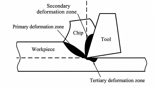
It can thus be concluded that during the vertical milling process, the temperature rise of the vertical milling cutter primarily originates from three sources:
The workpiece shear zone (first deformation zone), the tool-chip extrusion zone (second deformation zone), and the cutter edge friction zone (third deformation zone).
The distribution of heat sources during milling is shown in Figure 1.
Due to the complex geometry of the cutting edge, peripheral edge, and front and rear faces of an end mill, it is extremely difficult to directly measure the cutting edge temperature during the end milling process.
The heat source model derived from the Fourier solid heat conduction equation offers unique advantages;
Its principle involves first analyzing a point heat source and then constructing the temperature field through iterative superposition.
Given the method’s suitability for complex milling heat problems, this paper utilizes the heat source model to investigate the transient temperature distribution of a solid-body end mill.
Basic Assumptions for Moving Heat Source Modelling
First, we will solve for the temperature field of a continuously moving end mill during the machining process;
The coordinates of the temperature field along the machining path of the moving end mill are shown in Figure 2.
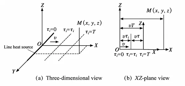
Assume that the machining path of the continuously moving end mill travels along the positive X-axis at a velocity v, where the length of the machining path is L, and the heat flux density is q;
The duration of the machining path’s motion is T. By applying geometric differentiation to decompose time into an infinite number of infinitesimal time intervals Δτi, we obtain that the heat load along the milling cutter’s cutting path during an infinitesimal time interval Δτi is qΔτi.
Let us assume that the starting time of the vertical milling cutter’s machining path is τi;
The time difference between τi and the end time T is τ, meaning that the duration during which the vertical milling cutter’s machining path generates heat is τ = T − τi. It follows that the straight-line distance from point M(x, y, z) to the end mill’s machining path is x − vτi.
Temperature Field Calculation Based on Fourier Heat Conduction Equation
Based on the heat conduction equation, we solve for the temperature increment Δθ at point M(x, y, z) over time T:

In the equation: c is the specific heat capacity of the medium; ρ is the density of the medium;
α is the thermal conductivity of the medium; and erf(·) is the error function.
Using the integration transformation formula, the temperature along the machining path of a continuous-motion end mill can be calculated as:

Finite Element Analysis of Temperature Fields Using Deform3D
According to the power calculation formula, the instantaneous power of a cutting tool during milling depends on the corresponding force and velocity.
During the milling process, it is assumed that the thermal load generated by the tool’s work is primarily due to shear deformation and friction;
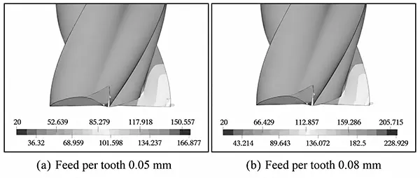
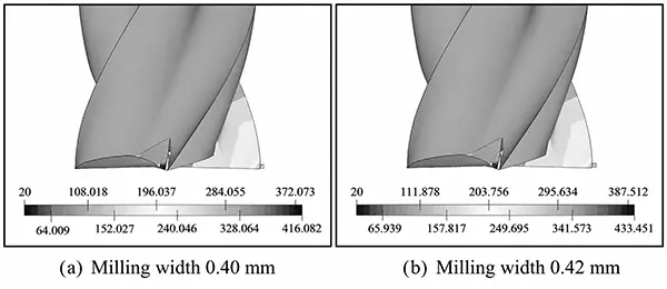
The temperature field distribution of the end mill varies with changes in machining parameters, as shown in Table 1.
Workpiece Material | End Mill Material | Number of Flutes | End Mill Diameter (mm) | End Mill Rake Angle (°) | End Mill Helix Angle (°) | Milling Conditions | Spindle Speed (rpm) |
|---|---|---|---|---|---|---|---|
Carbon Tool Steel | Cemented Carbide | 4 | 8 | 12 | 32 | Dry Cutting, Conventional Milling (Up Milling) | 3,500 |
Table 1. Milling Parameters
To systematically elucidate the underlying mechanisms, this paper employs the thermal analysis module of the Deform3D software to conduct numerical simulations using a single-factor strategy.
Researchers hold all other variables constant. They refer to the end mill structure.
They adjust only one machining parameter at a time. They separately assess how radial depth of cut, milling width, and feed per tooth affect the temperature field.
They also calculate the corresponding thermal loads. They identify temperature field variations of the end mill.
Researchers adjust one specific milling parameter in sequence during milling.
They keep all other milling parameters unchanged. They carry out finite element analysis.
The analysis examines the end mill’s temperature field under different power loads.
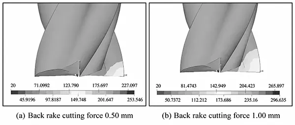
The temperature contour plots of the end mill under different back cutting depths are shown in Figure 3;
Those under different feed rates per tooth are shown in Figure 4; and those under different milling widths are shown in Figure 5.
Analysis of Peak Temperatures in End Mills
Researchers systematically analyze how milling parameters affect the peak temperature of end mills.
In this study, they adjust three key variables one by one: feed per tooth, depth of cut and milling width. All other conditions remain unchanged.
They use Equation (2) and Deform3D finite element simulation data of the temperature field.
They calculate thermomechanical coupled loads for each parameter set.
These loads are accurately mapped to heat-concentrated zones including the cutting edge, rake face, and flank face.
Establishment of Thermo-Mechanical Coupled Finite Element Model
A 3D thermo-mechanical finite element model is built on the Deform3D platform.
Adaptive meshing and local mesh refinement are adopted. The model realizes dynamic simulation of the full milling process.
Once the simulation finishes, researchers extract tool temperature data. They plot quantitative relationship curves in Figures 6–8.
The curves visually display how different milling parameters influence tool temperature rise.
Analysis of Parameter Sensitivity to Tool Peak Temperature
Figures 6 to 8 reveal the following. When a solid carbide end mill machines carbon steel, researchers take the peak temperature of the cutting edge as the optimization index.
This peak temperature has a strong positive correlation with the chosen cutting parameters.
Individually raising the back depth of cut, feed per tooth, or milling width will cause the peak temperature on the tool surface to rise monotonically.
In addition, the temperature contour plots of the milling cutter under different cutting parameters show that peak temperatures always gather near the rake face of the side cutting edge.
Therefore, if only temperature suppression is considered, the optimal process setup for the end mill requires minimizing these three parameters.
Multi-Objective Optimization Balancing Temperature Control and Machining Efficiency
However, in actual machining processes, material removal rate and machining efficiency must also be taken into account simultaneously;
Merely reducing these parameters may result in low machining efficiency.
Engineers design the optimal process scheme for end mills. They select cutting parameters using temperature data from different working conditions.
They adopt a multi-objective optimization framework. This method balances machining quality and production efficiency optimally.
Conclusion
Based on the heat source method, this paper establishes a mathematical model of the temperature field of an end mill.
Researchers used Deform3D. They simulated the temperature field of a solid carbide end mill.
The tests adopted different milling parameters: back depth, feed per tooth, and milling width.
They obtained heat maps showing the end mill’s temperature distribution.
They further systematically analyzed how milling parameters affect the tool’s temperature peaks.
The main conclusions of this paper are as follows:
(1) Increasing any one of the back cut depth, feed per tooth, or milling width will increase the overall thermal load on the end mill, thereby causing a significant rise in the temperature peak.
(2) Regardless of how the milling parameters are adjusted, the temperature peak consistently occurs in the front face region of the side cutting edge of the end mill.
This finding implies that, to effectively control the temperature rise of an end mill, priority should be given to simultaneously reducing these three parameters, while balancing production requirements and machining efficiency.