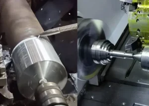
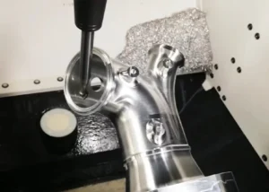
We can divide CNC machining into two major categories: low-speed machining and high-speed machining.
Conventional machines refer to those with a spindle speed of 8,000 rpm or less, while high-speed machines refer to those with a spindle speed exceeding 12,000 rpm.
Technicians define machines with spindle speeds between 8,000 and 12,000 rpm as quasi-high-speed machines.
This classification applies only to conventional machines.
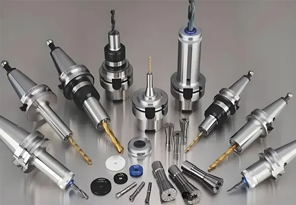
Manufacturers conventionally split CNC machining processes into three categories: roughing, semi-finishing, and finishing.
It is generally considered that roughing should use larger cutting tools (fly cutters and end mills) with greater cutting depths and feed rates (heavy cutting) to achieve rapid, high-volume material removal.
Finishing, on the other hand, relies on light cutting (small cutting depth and small feed rate) combined with higher spindle speeds and feed rates to achieve perfect surface finish.
End mills (or chamfering cutters) and fly cutters are used for finishing flat surfaces; end mills are used for finishing vertical walls;
And ball-nose cutters (or chamfering cutters) are used for finishing curved surfaces.
During the machining process, appropriate cutting tools should be selected based on the hardness of the workpiece material.
For materials such as plastic and wood, domestically produced white steel cutters may be used.
Copper, aluminum, and steels with a hardness of 38 Rockwell or less (such as No. 45 steel and “Wangpai” steel), imported steel cutters or high-quality domestically produced steel cutters should be selected.
For harder materials (such as hardened die steel), alloy cutters, titanium-coated cutters, or tungsten steel cutters should be prioritized.
In machining, it is essential to select appropriate cutting parameters; at the same time, to achieve optimal results from these parameters, the right cutting tools must be chosen.
These two aspects are mutually reinforcing; only by combining them can manufacturers effectively ensure the quality of CNC machine tools.
Cutting tools in a CNC machining center play a role similar to that of a chef’s knife; the quality of the tool directly determines the quality of the machined part.
However, this does not mean that simply selecting high-quality cutting tools will necessarily result in high-quality parts, as the selection of cutting parameters also plays a crucial role.
We must balance these two factors and make reasonable choices to produce parts that meet specifications.
Importance of Properly Selecting Cutting Tools and Cutting Parameters for CNC Machining Centers
Cutting tools are the most critical component of a machine tool; in other words, selecting the right cutting tools for a CNC machining center can improve the machine’s efficiency.
To ensure more efficient machining of parts, we must also control the cutting parameters.
If we can effectively manage both the selection of CNC machining center cutting tools and the cutting parameters, the machine tool will operate at its full potential, ensuring safe and smooth part machining.
For this reason, we must exercise caution and make well-informed choices.
This approach not only ensures work quality and improves efficiency but also effectively reduces production costs, serving as a key pathway for enterprises to enhance their economic benefits.
Basic Characteristics of Machining Center Cutting Tools
Generally speaking, in order to produce parts that meet quality standards and to meet the machining accuracy requirements of CNC machine tools, the requirements for cutting tools used in CNC machining centers are quite high.
Tools and tooling systems typically used in CNC machining centers generally share the following characteristics:
First, there are specific standards for the height of both the cutting inserts and tool holders.
Since operators run CNC machines automatically instead of manually, the machines lack the flexibility of human intervention;
Therefore, we must specify the heights of the inserts and tool holders to ensure consistent part quality.
Second, there are specific standards for setting the cutting parameters of the inserts.
This is essential to ensure that the produced parts meet standard specifications.
In essence, operators must match the inserts and their parameters to the material of the workpiece being machined;
Otherwise, significant discrepancies between the inserts and the workpiece can easily lead to damage to the workpiece.
Third, when selecting inserts, we must prioritize rigidity. The inserts we select must have good rigidity.
Finally, it is essential to choose toolholders with high strength; provided they offer good rigidity and wear resistance, the quality of the toolholders and cutting tools must meet the required standards.
Ultimately, the position of the inserts on the machine tool must be correct to ensure that the cut parts meet the standards.
It is essential to ensure the rotational angle of the toolholder, as well as the precision requirements for reinstallation and repeatability.
Machining Center Tool Materials
Commonly Used Tool Materials
Since the workpieces we manufacture are highly diverse, the materials used to make the tools also vary widely depending on the workpiece requirements.
High-speed steel, cemented carbide, ceramics, diamond, and coated cemented carbide are all materials commonly used to manufacture CNC tools.
However, the three most widely used materials among these are high-speed steel, cemented carbide, and coated cemented carbide.
Comparison of Tool Performance
Tool performance is directly related to the material used to manufacture the tool.
Among the materials we use for toolmaking, high-speed steel and coated high-speed steel are the best.
This is because the inherent properties of steel give tools made from high-speed steel and coated high-speed steel superior toughness.
Among common tool materials, tools made from coated cemented carbide have the highest hardness.
However, when machining special workpieces, we generally do not use cutting tools made from these materials due to the specific requirements of the workpiece.
They are used only when machining relatively hard materials.
Types of Cutting Tools
Since we need to manufacture a wide variety of parts, we also require a wide variety of cutting tools.
Engineers generally design these tools according to the requirements of the machined parts and the intended use of the cutting tool.
We can categorize the cutting tools we commonly use into three major categories:
The first is contouring tools, the second is hole-making tools, and the third consists of special-purpose tools.
Based on the above classification, we can see that this categorization is based on the tool’s intended use.
Contouring tools are further divided into three subcategories: face mills, end mills, and ball-end mills.
Engineers classify hole-machining tools into drills, reamers, and boring tools.
Face milling cutters feature the insert-type design we are familiar with, where the inserts and the tool body are mounted in a very orderly manner.
Such tools can increase production efficiency and improve the quality of the workpieces we produce.
However, not every machining operation requires this type of tool; we must select the appropriate workpiece and machine tool for installation.
These tools are generally convenient and efficient;
We can install them based on the dimensions of the workpiece we need, and we can also choose different tool models, which gives our operations greater flexibility.
The diameter of these tools is generally between 40 and 400 mm.
End Mills
End mills are currently the most commonly used cutting tools on machine tools.
End mills are further classified into solid-body and indexable-insert types.
The diameter of indexable-insert end mills is generally limited to 20 mm, whereas that of solid-body end mills is typically 20 mm or larger.
This is the primary distinction between the two types. These tools are generally well-suited for machining curved surfaces.
Ball-Nose Cutters
Ball-nose cutters are essentially cylindrical cutters with a spherical nose.
We use this type of tool specifically when machining relatively delicate workpieces.
When employing this tool, we are machining parts that require precise workmanship; such workpieces have higher surface quality requirements than standard parts.
However, due to the unique shape of the ball-nose cutter, it is not well-suited for flat milling.
The drill bits we commonly use are made of relatively hard materials, such as high-speed steel, cemented carbide, and coated cemented carbide.
We generally classify drill bits into two categories: center drills and standard twist drills.
Reamers are typically classified into three categories: high-speed steel reamers, cemented carbide-tipped reamers, and floating reamers.
There are numerous classifications of boring tools; generally, they are divided into rough boring tools, finish boring tools, floating boring tools, and so on.
For finish boring tools, we can adjust their precision and control the direction of the diameter.
Principles for Selecting Machining Center Cutting Tools
When selecting cutting tools for a machining center, the first principle we must consider is ensuring they are compatible with the material properties of our workpiece.
We must also take into account the machining process, the material of the cutting tool, and other factors to make a reasonable selection.
The choice of cutting tools is extremely important. Generally, when selecting cutting tools for a machining center, we must prioritize cost-effectiveness.
Our primary consideration should be to align with the actual machining conditions and select a material that offers the greatest benefit and best maximizes the value of the machining center cutting tool.
This process can certainly be quite tedious, but if we are able to select a suitable machining center cutting tool, it will be highly beneficial for our manufacturing process.
This is because a suitable cutting tool not only improves work efficiency but also reduces production costs while ensuring a higher yield rate for the finished workpieces.
While tool selection is one aspect, we must also exercise strict control during tool installation.
The tool should possess good rigidity, durability, and high precision.
Whenever possible, choose shorter tool shanks, as they enhance the tool’s rigidity.
When selecting tools, higher-priced options are naturally of better quality;
However, they may not offer the best value for money when machining workpieces with less demanding processing requirements.
Selecting Cutting Parameters
Once we have the appropriate cutting tools, it is crucial to select the right cutting parameters.
This is because cutting parameters directly affect the quality of the products we manufacture.
If we can select and set the cutting parameters appropriately, we can improve the efficiency of the machining process and enhance the quality of the machined parts.
In reality, there is no fixed set of numbers for making these selections;
Rather, we must continuously experiment and draw conclusions through practical experience to determine an appropriate range of cutting parameters.
Essentially, selecting cutting parameters involves determining the depth of cut, the side cut, and the cutting speed.
As long as we can effectively control these aspects, we can analyze the parameters during the machining process and then make appropriate selections for the cutting parameters.
| Tool Type | Depth (mm) | Step-Over | F (Feed Rate) | S (Spindle Speed) |
|---|---|---|---|---|
| Ø40R6 | 1 | 28 | 1200 | 1500 |
| Ø30R5 | 1 | 20 | 1500 | 1700 |
| Ø25R5 | 0.8 | 15 | 1500 | 1700 |
| Ø20R4 | 0.6 | 12 | 1600 | 1800 |
| Ø25R1 | 0.8 | 18 | 1400 | 1600 |
| Ø20R0.8 | 0.6 | 15 | 1500 | 1700 |
| Ø16R0.4 | 0.5 | 12 | 1400 | 1700 |
| Ø12R0.4 | 0.5 | 9 | 1300 | 1800 |
Table 1. Fly-Cutter Roughing Parameters Using 45# Steel as an Example
| Tool | Depth (mm) – Aluminum | Depth (mm) – Steel | Step-Over | F (Feed Rate) – Aluminum | F (Feed Rate) – Steel | S (Spindle Speed) – Aluminum | S (Spindle Speed) – Steel |
|---|---|---|---|---|---|---|---|
| Ø25 | 2.0 | 0.8 | 18 | 1800 | 1200 | 2000 | 1500 |
| Ø20 | 2.0 | 0.8 | 15 | 1700 | 1100 | 2000 | 1500 |
| Ø16 | 1.5 | 0.7 | 12 | 1700 | 1100 | 2200 | 1600 |
| Ø12 | 1.5 | 0.6 | 9 | 1600 | 1000 | 2200 | 1600 |
| Ø10 | 1.2 | 0.5 | 7 | 1500 | 900 | 2300 | 1700 |
| Ø8 | 1.0 | 0.5 | 6 | 1500 | 900 | 2400 | 1700 |
| Ø6 | 1.0 | 0.5 | 4 | 1500 | 800 | 2400 | 1700 |
| Ø5 | 0.8 | 0.4 | 3 | 1200 | 700 | 2500 | 1800 |
| Ø4 | 0.8 | 0.4 | 2.5 | 1000 | 600 | 2600 | 1800 |
| Ø3 | 0.5 | 0.3 | 2 | 800 | 500 | 2800 | 1900 |
| Ø2 | 0.3 | 0.2 | 1 | 600 | 400 | 2900 | 2000 |
| Ø1 | 0.2 | 0.1 | 0.5 | 500 | 300 | 3000 | 2200 |
Table 2. Imported White-Steel Face Mill for Rough Milling Aluminum Alloy and 45# Steel
| Tool | Stock Allowance Before Machining – Aluminum (mm) | Stock Allowance Before Machining – Steel (mm) | Step-Over (mm) | S (Spindle Speed) – Aluminum (rpm) | S (Spindle Speed) – Steel (rpm) | F (Feed Rate) – Aluminum (mm/min) | F (Feed Rate) – Steel (mm/min) |
|---|---|---|---|---|---|---|---|
| Ø20R10 | 0.25 | 0.15 | 0.30 | 2200 | 1800 | 2300 | 1500 |
| Ø16R8 | 0.25 | 0.15 | 0.30 | 2200 | 1800 | 2300 | 1500 |
| Ø12R6 | 0.20 | 0.12 | 0.25 | 2500 | 2000 | 2600 | 1800 |
| Ø10R5 | 0.20 | 0.12 | 0.25 | 2500 | 2000 | 2600 | 1800 |
| Ø8R4 | 0.20 | 0.12 | 0.20 | 2600 | 2300 | 2400 | 1600 |
| Ø6R3 | 0.15 | 0.10 | 0.15 | 2800 | 2400 | 2300 | 1500 |
| Ø4R2 | 0.12 | 0.08 | 0.12 | 3000 | 2500 | 1800 | 1200 |
| Ø3R1.5 | 0.10 | 0.06 | 0.08 | 3200 | 2600 | 1600 | 900 |
| Ø2R1 | 0.08 | 0.05 | 0.06 | 3500 | 2700 | 1300 | 600 |
| Ø1R0.5 | 0.06 | 0.04 | 0.04 | 3800 | 2800 | 1200 | 500 |
Table 3. White-Steel Ball-Nose End Mill for Aluminum Alloy and 45# Steel
| Tool | Stock Allowance Before Machining – 45# Steel (mm) | Stock Allowance Before Machining – Stainless Steel (mm) | Step-Over (mm) | S (Spindle Speed) – 45# Steel (rpm) | S (Spindle Speed) – Stainless Steel (rpm) | F (Feed Rate) – 45# Steel (mm/min) | F (Feed Rate) – Stainless Steel (mm/min) |
|---|---|---|---|---|---|---|---|
| Ø20R10 | 0.20 | 0.15 | 0.25 | 2400 | 2400 | 2000 | 1800 |
| Ø16R8 | 0.20 | 0.12 | 0.25 | 2400 | 2400 | 2000 | 1800 |
| Ø12R6 | 0.15 | 0.10 | 0.20 | 2600 | 2700 | 2200 | 2000 |
| Ø10R5 | 0.15 | 0.10 | 0.20 | 2600 | 2700 | 2200 | 2000 |
| Ø8R4 | 0.15 | 0.10 | 0.15 | 2800 | 2800 | 2000 | 1600 |
| Ø6R3 | 0.12 | 0.08 | 0.12 | 3000 | 3000 | 1800 | 1500 |
| Ø4R2 | 0.10 | 0.06 | 0.08 | 3200 | 3200 | 1300 | 1000 |
| Ø3R1.5 | 0.08 | 0.05 | 0.06 | 3500 | 3500 | 1000 | 700 |
| Ø2R1 | 0.07 | 0.04 | 0.05 | 3800 | 3800 | 600 | 500 |
| Ø1R0.5 | 0.05 | 0.03 | 0.03 | 4000 | 4000 | 500 | 400 |
Table 4. Carbide Ball-Nose End Mill for Finishing 45# Steel and Stainless Steel
| Tool | Maximum Cutting Amount – 45# Steel (mm) | Maximum Cutting Amount – Stainless Steel (mm) | Maximum Cutting Depth – 45# Steel (mm) | Maximum Cutting Depth – Stainless Steel (mm) | S (Spindle Speed) – 45# Steel (rpm) | S (Spindle Speed) – Stainless Steel (rpm) | F (Feed Rate) – 45# Steel (mm/min) | F (Feed Rate) – Stainless Steel (mm/min) |
|---|---|---|---|---|---|---|---|---|
| Ø16 | 0.30 | 0.25 | 40 | 30 | 1600 | 1600 | 800 | 700 |
| Ø12 | 0.25 | 0.20 | 35 | 25 | 1700 | 1700 | 800 | 700 |
| Ø10 | 0.20 | 0.15 | 30 | 20 | 1700 | 1700 | 750 | 650 |
| Ø8 | 0.15 | 0.10 | 25 | 20 | 1800 | 1800 | 650 | 600 |
| Ø6 | 0.15 | 0.10 | 20 | 15 | 2000 | 2000 | 600 | 500 |
| Ø5 | 0.10 | 0.08 | 15 | 10 | 2200 | 2200 | 500 | 400 |
| Ø4 | 0.08 | 0.06 | 10 | 7 | 2300 | 2300 | 400 | 300 |
| Ø3 | 0.06 | 0.05 | 5 | 3 | 2500 | 2500 | 400 | 300 |
| Ø2 | 0.20 | 0.15 | 1 | 1 | 3000 | 3000 | 700 | 500 |
| Ø1 | 0.15 | 0.10 | 0.5 | 0.5 | 3500 | 3500 | 600 | 400 |
Table 5. Carbide Face Mill for 45# Steel and Stainless Steel
| Tool Diameter | Maximum Cutting AmountAluminum Alloy | Maximum Cutting AmountNo. 45 Steel | Maximum Cutting DepthAluminum Alloy | Maximum Cutting DepthNo. 45 Steel | S (Spindle Speed)Aluminum Alloy | S (Spindle Speed)No. 45 Steel | F (Feed Rate)Aluminum Alloy | F (Feed Rate)No. 45 Steel |
|---|---|---|---|---|---|---|---|---|
| Ø16 | 0.4 | 0.25 | 50 | 35 | 1700 | 1600 | 1200 | 800 |
| Ø12 | 0.35 | 0.2 | 40 | 30 | 1700 | 1600 | 1000 | 700 |
| Ø10 | 0.3 | 0.15 | 35 | 20 | 1800 | 1700 | 900 | 600 |
| Ø8 | 0.25 | 0.1 | 30 | 15 | 2000 | 1800 | 900 | 550 |
| Ø6 | 0.2 | 0.1 | 25 | 10 | 2200 | 1900 | 800 | 500 |
| Ø5 | 0.15 | 0.08 | 20 | 8 | 2300 | 2000 | 700 | 450 |
| Ø4 | 0.5 | 0.3 | 2 | 1.2 | 2600 | 2200 | 1200 | 1100 |
| Ø3 | 0.3 | 0.2 | 1.5 | 1 | 2700 | 2400 | 1000 | 800 |
| Ø2 | 0.25 | 0.2 | 1 | 0.5 | 2800 | 2500 | 800 | 500 |
| Ø1 | 0.2 | 0.15 | 0.8 | 0.3 | 3000 | 2600 | 600 | 400 |
Table 6 — HSS Flat End Mill (Finishing) — Aluminum Alloy & No. 45 Steel