During machining in blind zones, the positional and rotational stability of the tool-workpiece interface deteriorates sharply due to system stiffness anisotropy and sudden changes in the direction of cutting forces.
This leads to frequent cutting flutter, increased tool wobble, and a forced reduction in feed rate, thereby severely compromising the cutting accuracy of CNC machine tools.
Consequently, overcoming the technical bottleneck of feed rate limitations caused by vibration disturbances during blind-zone machining has become a current research focus.
Yin Jia et al. proposed a digital twin-based method for regulating machine tool feed rates using fuzzy neural networks.
However, this method lacks a direct mechanical compensation mechanism for the physical response characteristics of the underlying mechanical transmission system under conditions of sudden stiffness changes, such as in blind zones.
Qu Xingyu et al. proposed a model-free adaptive sliding mode control strategy with improved preset performance for ball screw feed systems.
However, the control effectiveness of this method relies heavily on the mechanical stiffness and damping characteristics of the feed system and cannot effectively interrupt the physical coupling process of “tool clearance—increased load—intensified vibration.”
Addressing the shortcomings of existing methods, this paper investigates feed rate control technology for CNC machine tools under the influence of machining blind zones.
Gradient Control of Transmission System Stiffness for Excitation Force Rheology in Blind Zones
This paper proposes a targeted method for regulating the stiffness gradient of transmission systems, which enhances the static and dynamic stiffness reserves of the transmission chain through refined mechanical operations.
For ball screw assemblies, the axial contact stiffness primarily depends on the preload between the nut and the screw raceway.
Based on Hertzian contact theory, we express the relationship among the axial contact deformation δs of the ball screw assembly, preload Fp, and axial working load Fa as:

In the equation, Cs is a structural coefficient related to the geometric dimensions and material properties of the lead screw.
For the guide rail-slider interface, the clearance between sliding surfaces and the oil film state greatly influence contact stiffness.
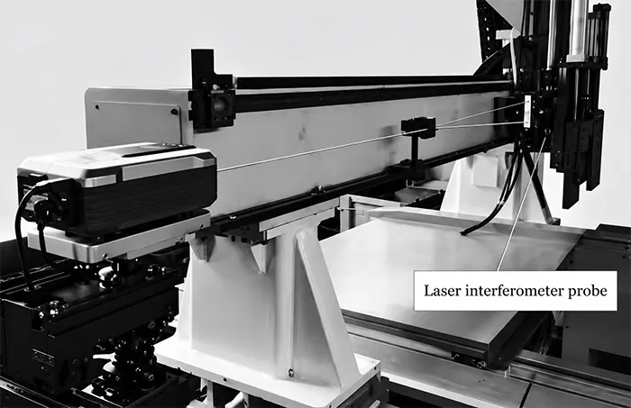
We adopt a micro-feed grinding and lapping process to eliminate adverse clearance effects on the guide rail clamping plate.
By reducing the residual equivalent clearance after lapping, we improve the vibration resistance and dynamic response of the guide rail pair under cutting loads, thereby ensuring stable motion guidance for moving components under complex dead‑zone force conditions.
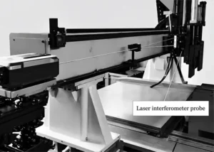
The micro-feed grinding and lapping device for the guide rail clamping plate clearance is shown in Figure 1.
This study implements two technical improvement measures.
The research reasonably corrects the gradient increment of screw preload and applies micro-feed grinding and lapping to optimize the clearance of the guide rail clamping plate.
These methods effectively solve the insufficient dynamic stiffness of the transmission system.
This issue originally arises from force flow excitation in the blind zone.
Friction-Impact Composite Energy Dissipation Mechanism and Passive Broadband Damping
Lateral vibration excitation occurs during cutting operations. It drives the damping block to generate relative motion inside the cavity.
Periodic collision and sliding friction occur between the damping block and the inner cavity wall.
This converts vibrational mechanical energy into thermal energy and fully dissipates it.
We regard this process as a continuous-body vibration system equipped with an extra nonlinear damping term.
The tool shank is simplified to the Euler–Bernoulli beam equation, taking into account the equivalent nonlinear damping force Fd(x) generated by the damping block.
The vibrational partial differential equation can be written as:

In the equation: E is the elastic modulus of the tool shank material; I is the moment of inertia of the cross section; ρ is the density;
A is the cross-sectional area; c is the internal damping coefficient of the material; xd is the installation position of the damping block;
L is the tool shank overhang length; Fc(t) is the cutting force in the blind zone;
δ is the amplitude of the sudden increase in runout when flutter occurs; x is the positional coordinate along the tool shank axis;
y(x, t) is the lateral displacement of the tool shank at position x at time t.
The optimized built-in damping block structure significantly enhances damping near the natural frequency of the tool shank system during blind-zone cutting, effectively suppressing the tool’s radial runout.
Experimental Analysis
Experimental Platform, Measuring Instruments and Workpiece Configuration
The experiment established a real-time monitoring system based on lever-type mechanical-dynamic coupling measurements.
We equip the machine tool spindle with a vibration-damping tool shank that contains an internal cavity for a high-density tungsten alloy damping block.
We measure cutting forces via a Kistler 9129AA rotary force transducer and detect tool radial runout using a lever-type dial indicator paired with a dynamic signal acquisition instrument.
The workpiece was a prefabricated TC4 titanium alloy block.
We machined a deep cavity on the top of the block and set the blind-area machining position at the transition arc section of the deep cavity’s bottom corner.
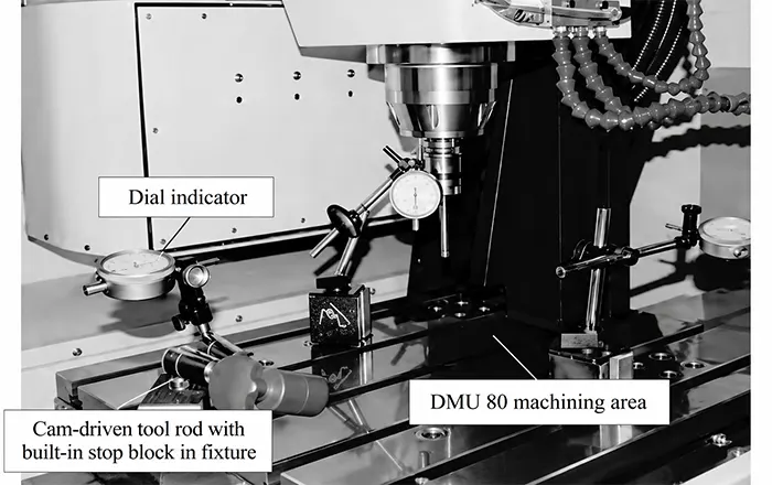
Figure 2 presents the experimental setup, and Table 1 lists the stiffness control parameters of the drive system.
| Adjustment Component | Parameters Before Adjustment | Parameters After Adjustment |
|---|---|---|
| Ball Screw Nut (X-axis) | Preload: 1,800 N | Gradient increment: +200 N |
| Linear Guide Slider (X-axis) | Pressure plate clearance: 5–8 μm; oil film thickness: 1–2 μm | After precision lapping and matching, residual clearance ≤ 1.5 μm; contact area ≥ 85% |
| Spindle Bearing (Preload) | Factory preload: 600 N | Compensated in gradient increments of +50 N |
Table 1. Transmission System Stiffness Adjustment Parameters
Experimental Scheme and Definition of Evaluation Indicators
1. Two-stage Experimental Design
The experiment was divided into two stages:
The first stage involved the initial condition without drive system control and using a standard tool shank, which was used to identify the original “speed-feed” characteristic;
The second stage involved testing the optimized state after applying the method described in this paper.
2. Definition of Evaluation Indices for Cutting Performance
Among these parameters, the mean peak value of tool radial runout @1,000 refers to the time-domain mean peak value of the tool’s radial runout amplitude at a given feed rate (1,000 mm·min⁻¹), which is used to characterize the degree of dynamic runout of the tool during the cutting process.
A smaller value indicates that the tool shank system has a stronger ability to suppress vibrations.
Workpiece surface roughness Ra@1,200 refers to the arithmetic mean deviation of the workpiece surface profile after machining at a given feed rate (1,200 mm·min⁻¹), which is used to quantify microscopic surface irregularities.
A smaller value indicates higher surface quality. The comparison of key indicators for cutting stability during blind-area machining before and after optimization is shown in Table 2.
| Indicator | Before Optimization | After Optimization |
|---|---|---|
| Critical Chatter Feed Rate (mm/min) | 780 | 1,350 |
| Maximum Stable Cutting Feed Rate | 750 mm/min (reduced based on experience) | 1,300 mm/min (safe operation) |
| Number of Cuts per Single Feed Stroke | 12 (multiple tool changes required) | 28 (completed continuously) |
| Mean Radial Tool Deflection @ 1,000 | 28.6 μm (chatter occurred) | 16.3 μm (stable) |
| Workpiece Surface Roughness Ra @ 1,200 (μm) | — | 1.26 |
Table 2. Comparison of Key Cutting Stability Indicators in Blind-Area Machining Before and After Optimization
3. Quantitative Comparison of Key Performance Indicators Before and After Optimization
As shown in Table 2, after implementing stiffness gradient control and a damping vibration-suppression tool shank, the critical chattering feed rate increased from 780 mm·min⁻¹ to 1,350 mm·min⁻¹, indicating that the machine tool can operate at higher feed rates while avoiding chattering.
In actual production, the maximum stable cutting feed rate can be increased to 1,300 mm·min⁻¹.
The number of cuts per feed stroke increased from 12 to 28, significantly reducing idle travel time and improving machining efficiency.
The experiment was conducted at a feed rate of 1000 mm·min⁻¹. The optimized tool achieved a 43% reduction in the average peak radial runout compared with the original tool.
This result indicates that the improved stiffness of the transmission system contributes to vibration suppression.
Moreover, the energy dissipation mechanism of the tool shank further restrains tool-triggered vibration.
The machining test was carried out at a feed rate of 1200 mm·min⁻¹.
The optimized workpiece achieved a surface roughness of 1.26 μm. This surface quality satisfies the precision machining requirements for aerospace components.
In contrast, the unoptimized process produced severe chatter marks. Such undesirable surface defects rendered normal machining infeasible.
Microscopic Surface Topography Comparison and Mechanism Verification
This test aims to compare workpiece surface quality. The comparison targets the conditions before and after adopting the proposed method.
We conduct all experiments under blind-area machining conditions and evaluate the machining quality from the perspective of microscopic topography. Figure 3 presents the comparative results.
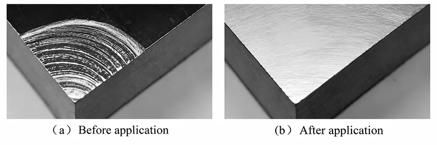
As shown in Figure 3, before application, the front rake angle region exhibits distinct fish-scale-like vibration marks with a chaotic pattern and varying depths, displaying a periodic alternation of light and dark areas.
This is caused by the tool’s radial runout exceeding the critical threshold, resulting in periodic contact and separation between the tool’s rear face and the machined surface;
The stiffness anisotropy at the bottom corner of the blind zone exacerbated the cutting forces, leading to fluctuations in material removal thickness and a severe deterioration in surface quality.
After applying the method described in this paper, the machined texture became uniform and fine; regular tool cutting marks were observable along the feed direction, with no obvious vibration marks or fish-scale patterns.
The surface was flat and smooth, transverse vibration marks were completely eliminated, and the workpiece exhibited a uniform metallic luster.
Comparative verification was performed at the microscopic level. The results validate the effectiveness of the friction–impact composite energy dissipation mechanism.
This mechanism can significantly suppress high-frequency vibration during machining.
The results also demonstrate the compensatory capability of stiffness gradient control. This control method effectively resists tool deflection disturbances.
This approach effectively raises the cutting stability threshold for machining in blind areas and significantly improves both the number of cuts per feed stroke and the average feed rate.
Conclusion
This paper focuses on the challenges posed by machining blind spots to feed rate control in CNC machine tools.
This study establishes a three-tier control system for machining vibration suppression. The system consists of three core technical measures.
These measures include incremental calibration of preload gradients, micro-feed grinding and lapping of guideway-clamping plate clearances, and a friction-impact composite energy-dissipating tool shank.
The proposed system realizes precise suppression of excitation force flows during machining.
Future work will focus on decoupling dynamic characteristics in multi-axis simultaneous machining scenarios and researching parameter-adaptive optimization methods based on digital twins.