Aluminum alloys are widely used in the aerospace and automotive manufacturing industries due to their light weight, high strength, and good thermal conductivity.
Although high-speed cutting technology can significantly improve machining efficiency, improper cutting parameters can easily lead to rapid tool wear, reduced precision, and increased energy consumption.
Current research has primarily focused on the effects of individual parameters, with a lack of systematic analysis of the coupling mechanisms among cutting forces, temperature, and tool wear.
Based on the mechanical properties of aluminum alloys during high-speed cutting, this paper combines finite element simulation with experimental validation to investigate the influence of process parameters on machining efficiency and quality.
A multi-objective optimization model is developed, and an efficient machining strategy is proposed to provide technical support for the manufacturing of precision aluminum alloy parts.
Mechanical Properties of High-Speed Cutting of Aluminum Alloys and Their Impact on Efficiency
Coupled Behavior of Cutting Forces, Cutting Temperature, and Tool Wear
During high-speed machining of aluminum alloys, we increase the cutting speed to 800–1200 m/min, which raises the shear zone temperature to 300–450 °C.
Material softening reduces cutting forces by 15%–25%. However, the intensified temperature gradient within the tool-chip contact zone accelerates wear on the tool rake face.
Once the temperature exceeds the critical threshold, thermal fatigue strips off the tool coating and increases the tool wear rate exponentially.
Tool wear serves as a critical factor that induces fluctuating cutting forces.
Specifically, we observe that every 0.1 mm increase in the width of the tool wear zone raises the amplitude of cutting force fluctuation by 8%–12% and elevates the cutting temperature by 18–25 °C.
This phenomenon creates a harmful force-heat-wear vicious cycle, which directly limits the overall machining efficiency and tool service life.
The Impact of Machining Stability on Efficiency Under High-Speed Cutting Conditions
Machining stability is a key factor limiting efficiency improvements.
Insufficient rigidity in the machining system readily induces flutter. When the amplitude exceeds 15 μm, we have to reduce the material removal rate by 30% to 40%.
Because aluminum alloys feature a low elastic modulus (approximately 70 GPa), the workpiece deforms substantially. We must therefore restrict the axial depth of cut to 0.5–1.5 mm.
When the spindle speed approaches the system’s natural frequency, the vibration amplitude increases by 2 to 3 times, resulting in an efficiency loss of up to 50%.
Improper cutting parameters lead to difficulty in chip evacuation, reducing the actual cutting time to 65%–75% of the total cycle time.
For every 10 mm increase in tool overhang, the stable cutting range shrinks by 20%, and the machining cycle time increases by 15%–25%.
Patterns of How Machining Parameters Affect Efficiency and Part Quality
Analysis of the Combined Effects of Cutting Speed, Feed Rate, and Cutting Depth
The influence of cutting parameters on machining efficiency exhibits significant interactions.
When the cutting speed is increased from 600 m/min to 1000 m/min, the material removal rate increases by 67%;
However, surface roughness deteriorates sharply when the feed rate exceeds 0.25 mm/r.
The combined effect of these three parameters on machining efficiency can be characterized by the material removal rate:

In the equation: Q is the material removal rate, mm³/min; v is the cutting speed,m/min; f is the feed rate, mm/r; ap is the depth of cut, mm.
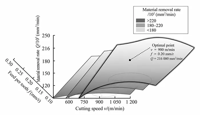
Experiments show that when v = 900 m/min, f = 0.20 mm/r, and ap = 1.2 mm, Q = 216,000 mm³/min, representing a 42% increase in efficiency compared to conventional parameters, while maintaining a surface roughness Ra of 0.9 μm, thereby achieving an optimal balance between efficiency and quality (see Figure 1).
Mechanisms for Regulating Cutting Tool Geometric Parameters and Cutting Stability
Cutting tool geometric parameters directly influence the distribution of cutting forces and machining stability.
Increasing the rake angle from 8° to 12° reduces cutting forces by 18%, but increases the risk of chipping.
When the clearance angle is maintained between 10° and 12°, tool-workpiece friction is minimized, and vibration amplitude is reduced by 35%.
A helix angle of 35° reduces the axial force component by 28% and effectively suppresses workpiece deformation.
A cutting edge rounding radius within the range of 15–25 μm ensures edge strength while avoiding the extrusion effect, keeping cutting force fluctuations within ±8%.
Variable-helix end mills disperse cutting force pulses through phase differences, increasing the critical depth of cut for chatter by 40%, expanding the stable cutting range, and improving machining efficiency by 25%–30%.
A Study on the Application of Simulation in Machining Optimization
Prediction of Cutting Forces, Temperature, and Tool Wear Using Finite Element Analysis
We establish a three-dimensional finite element model for high-speed cutting of aluminum alloys based on the Johnson-Cook constitutive model.
We apply adaptive refinement techniques to generate the mesh and control the element size in the cutting zone at 10 μm.
We express the material flow stress as:

In the equation: σ is the yield stress, in MPa; ε is the equivalent plastic strain; εs is the equivalent plastic strain rate, in s⁻¹; εs₀ is the reference strain rate, taken as 1 s⁻¹;
T is the instantaneous temperature in the cutting zone, in °C; Troom is room temperature, taken as 20 °C;
Tmelt is the melting point of the material; for aluminum alloy, it is taken as 660 °C; A is the yield strength, taken as 324 MPa;
B is the hardening modulus, taken as 114 MPa; n is the hardening index, taken as 0.42;
C is the strain rate sensitivity coefficient, taken as 0.002; m is the temperature softening index, taken as 1.34.
When v = 900 m/min and f = 0.20 mm/r, the calculated cutting force Fc is 185 N and the cutting temperature T is 385 °C, with an error of <8% compared to the measured values.
The maximum wear rate on the tool’s rake face occurs 0.15 mm from the cutting edge, and the predicted tool life is 45 min, providing a basis for parameter optimization.
Development of a Simulation-Based Optimization Model for Tool Life and Machining Efficiency
A multi-objective optimization model was developed with the goals of maximizing machining efficiency and optimizing tool life.
Tool life was calculated using the modified Taylor formula:

In the equation: T is the tool life, in minutes; C is the material constant, taken as 2.8 × 10⁸; α = 3.5, β = 0.8, and γ = 0.6 are the exponents;
K is the correction factor (taken as 1.2 to account for the effects of cooling and coating).
When v = 850 m/min, f = 0.18 mm/r, and ap = 1.0 mm, the calculation yields T = 52 min and a machining efficiency Q = 153,000 mm³/min.
We solve for the Pareto optimal solution set using the NSGA-II algorithm and obtain 15 sets of non-dominated solutions.
When the weighting coefficients were set to 0.6 for efficiency and 0.4 for tool life, the optimal parameter combination was v = 920 m/min, f = 0.22 mm/r, and ap = 1.1 mm, resulting in a 38% improvement in comprehensive performance metrics.
Virtual Experiments for Parameter Optimization and Machining Plan Design
We conduct virtual parameter optimization experiments using the response surface method and design the machining plan according to the following principles:
1) During the roughing stage, a deep-cut strategy was adopted (ap = 2.0–2.5 mm, v = 700–800 m/min) to achieve a high material removal rate;
This stage accounted for 65% of the total machining time in terms of efficiency.
2) The semi-finishing stage employs moderate parameters: ap = 0.8–1.2 mm and f = 0.15–0.20 mm/r, balancing efficiency and surface quality.
3) During the finishing stage, the feed rate is reduced to f = 0.08–0.12 mm/r, while v is increased to 1000–1200 m/min to ensure Ra ≤ 0.8 μm.
4) Toolpath optimization employs helical interpolation to avoid the impact of vertical plunging, reducing cutting force fluctuations by 40%.
5) Minimal quantity lubrication (MQL) is used for cooling, with an air pressure of 0.6 MPa and an oil mist flow rate of 50 mL/h, reducing cutting temperature by 55 °C and extending tool life by 32%.
Implementation and Quantitative Evaluation of High-Efficiency Machining Solutions
Quantitative Analysis of Machining Efficiency, Energy Consumption, and Costs
After implementing the optimization plan, the machining time per part was reduced from 85 minutes to 58 minutes, representing a 32% increase in efficiency.
The average spindle cutting power was 3.2 kW, and energy consumption per part decreased from 1.45 kW·h to 1.23 kW·h, a reduction of 18%.
Extended tool life reduced tooling costs from 18 yuan per piece to 13 yuan per piece, and the total machining cost fell from 56 yuan per piece to 46 yuan per piece, resulting in cost savings of 10,000 yuan for a production run of 1,000 pieces.
Evaluation Metric | Before Optimization | After Optimization | Improvement (%) |
|---|---|---|---|
Machining Time per Part (min) | 85 | 58 | 31.8 |
Material Removal Rate (mm³/min) | 164,000 | 216,000 | 31.7 |
Energy Consumption per Part (kWh) | 1.45 | 1.23 | 15.2 |
Tooling Cost (CNY/part) | 18 | 13 | 27.8 |
Total Cost (CNY/part) | 56 | 46 | 17.9 |
Table 1. Comparison of Machining Efficiency and Costs Before and After Optimization
Verification of Part Surface Quality, Dimensional Accuracy, and Reliability
A coordinate measuring machine (CMM) inspected 30 samples, achieving dimensional accuracy of IT7 grade, positional deviation ≤0.015 mm, and a 100% pass rate. Surface roughness Ra remained stable at 0.75–0.85 μm, with residual compressive stress of -45 MPa.
Metallographic analysis revealed a surface work-hardened layer approximately 12 μm thick, with no microcracks detected.
After continuous machining of 500 parts, the standard deviation of dimensions was σ = 0.008 mm, and fatigue life was improved by 22% compared to the traditional method, ensuring reliability.
Comprehensive Performance Evaluation and Process Feasibility Analysis
An evaluation system was established based on four dimensions—efficiency, quality, cost, and environmental protection.
The optimized solution achieved a comprehensive score of 8.6 points, representing a 35% improvement over the traditional process.
Implementation of the process requires a high-speed machining center with a spindle speed of ≥12,000 r/min.
The investment in equipment retrofitting is approximately 150,000 yuan, with a payback period of 8 months.
After continuous production of 1,000 parts, the scrap rate was <0.5%, meeting the conditions for widespread adoption.
Evaluation Category | Specific Indicator | Weight | Score Before Optimization | Score After Optimization |
|---|---|---|---|---|
Machining Efficiency (0.35) | Material Removal Rate | 0.20 | 6.5 | 8.8 |
Machining Time | 0.15 | 6.0 | 8.5 | |
Part Quality (0.30) | Surface Roughness | 0.15 | 7.0 | 8.6 |
Dimensional Accuracy | 0.15 | 7.5 | 8.8 | |
Economic Cost (0.25) | Machining Cost | 0.15 | 6.0 | 8.2 |
Tool Life | 0.10 | 5.8 | 8.0 | |
Environmental Sustainability (0.10) | Energy Consumption | 0.10 | 6.5 | 8.4 |
Overall Score | 1.00 | 6.4 | 8.6 |
Table 2. Comprehensive Performance Evaluation Criteria
Conclusion
This paper investigates methods for optimizing the machining efficiency of high-speed cutting of aluminum alloys and reveals the coupling mechanism among material microstructure, cutting parameters, and machining stability.
By using finite element simulation to predict cutting forces, temperature, and tool wear, a multi-objective optimization model was established.
Experiments showed that the optimized parameters increased material removal rate by 32%, achieved a surface roughness of Ra 0.8 μm, extended tool life by 28%, and reduced overall costs by 18%.
This study provides a theoretical basis for selecting high-speed cutting processes for aluminum alloys and holds engineering application value for the machining of parts in fields such as aerospace and automotive manufacturing.
Future research could further investigate the effects of tool coatings and cooling methods.