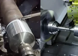
In the machining of mechanical shaft components, slender shafts are a typical workpiece type that is widely used yet extremely challenging to machine.
Within the industry, shaft components with a length-to-diameter ratio greater than 25 are generally defined as slender shafts.
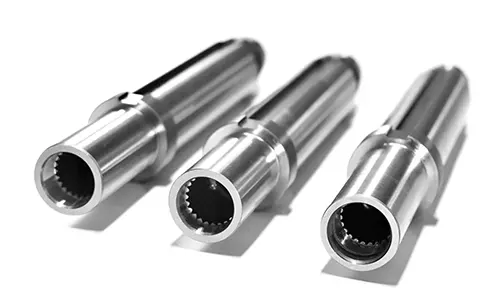
Thanks to their lightweight nature and suitability for precision transmission systems, they are widely used in precision equipment, automated machinery, machine tool components, and other fields.
However, slender shafts have extremely low inherent rigidity, great length, and small diameter.
These characteristics make them highly prone to bending deformation, tool vibration, dimensional deviations, and substandard surface roughness during machining.
These issues remain a persistent challenge in machining production.
To ensure machining accuracy, a high yield rate, and operational stability for slender shafts, it is essential to carefully control the critical details throughout the entire machining process.
Today, we will provide a detailed breakdown of the key considerations for machining slender shafts to help you achieve efficient and high-quality production.
Optimizing Workpiece Clamping Methods
Optimize workpiece clamping methods to mitigate thermal deformation and force deviations.
Clamping is the first step in machining slender shafts and a fundamental process for controlling deformation issues.
During the rough machining stage of slender shafts, large cutting allowances and high cutting forces make the workpiece highly susceptible to deformation caused by external compression.
At the same time, the high temperatures generated during the cutting process can cause thermal expansion of the workpiece.
If the clamping method is rigid, it will directly lead to workpiece bending and dimensional deviations.
For conventional rough machining scenarios, the top-clamping method is recommended, paired with a flexible tailstock center.
The key advantage of this clamping method is that it allows for axial expansion and contraction of the workpiece, perfectly accommodating thermal expansion caused by high cutting temperatures and effectively preventing bending deformation resulting from thermal expansion under pressure.
However, in high-intensity machining scenarios involving high-speed cutting or heavy cutting with large material removal, the top-clamping method lacks sufficient stability.
In such cases, it is necessary to switch to the clamp-and-pull method, which secures the workpiece with greater clamping rigidity.
This eliminates issues such as loosening, misalignment, and vibration during machining, ensuring the stability of the machining reference.
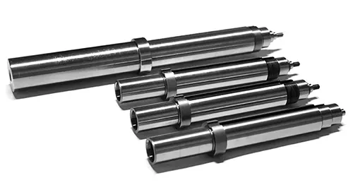
Optional Adaptive Tool Holder
Opt for an adaptive tool holder to suppress vibration and radial deformation.
The tool holder is an indispensable auxiliary fixture for machining slender shafts and a key component for addressing workpiece radial deformation and cutting chatter marks.
During the machining of slender shafts, radial cutting forces continuously act on the workpiece’s weakest areas, causing elastic deflection and ultimately resulting in defects such as cylindricity deviations and surface chatter marks.
Proper use of a tool follower can effectively counteract these radial cutting forces, firmly support the workpiece, and significantly improve machining stability.
It is crucial to note that the installation accuracy of the tool follower directly determines machining quality.
During installation, it is essential to ensure that the center of the workpiece support is perfectly aligned with the center of the machine tool center point.
If the center is too high or too low, it will cause uneven force distribution on the workpiece.
Not only will this fail to prevent deformation, but it will also exacerbate workpiece bending, cause tool wear, and directly compromise the surface accuracy of the workpiece.
Additionally, the support force of the workpiece support must be adjusted before machining to ensure it fits snugly against the workpiece without applying excessive pressure, thereby accommodating different cutting conditions for roughing and finishing operations.
Proper Use of Reverse Feed Technology
Proper use of the reverse feed process reduces bending deformation.
Conventional forward-feed turning processes cause slender shafts to undergo axial compression under cutting forces.
For slender shafts with low rigidity, this can easily lead to bending deformation, making it difficult to ensure straightness accuracy.
To address this challenge, reverse feed processes can be employed in finishing and high-precision machining applications, in conjunction with a Karla fixture.
The core principle of reverse feed is to alter the direction of cutting forces, converting the workpiece’s axial compressive force into tensile force.
This prevents bending caused by compression at its source, significantly improving the straightness and machining accuracy of slender shafts.
In addition, it is essential to distinguish between rough and finish machining conditions when selecting specialized turning tools:
For rough machining, choose high-strength, wear-resistant turning tools suitable for heavy-cut machining;
For finish machining, select precision turning tools with a fine tip radius and sharp cutting edges to minimize cutting marks and ensure the workpiece surface roughness meets specifications.
Summary
The core challenges in machining slender shafts ultimately boil down to poor rigidity, susceptibility to thermal deformation, and susceptibility to vibration.
To improve machining quality, there is no need for complex processes; simply focus on four key details—clamping methods, toolpost alignment, feed parameters, and tool selection—and specifically address common issues such as deformation, tool vibration, and dimensional deviations.
This approach will consistently improve the finished accuracy and machining efficiency of slender shafts, meeting the requirements of various precision applications.