
1. Hook: Why 0.01 mm Can Decide Pass or Scrap
In CNC machining, the difference between a good part and a rejected batch is often not visible to the eye—it is hidden at the scale of 0.01 mm. A real-world scenario illustrates this clearly: a precision-machined shaft passes all in-process checks with calipers, yet fails during final assembly because it does not fit into a mating bearing housing.
This is not an uncommon situation in manufacturing. A deviation of just a few microns can cause:
- Excessive friction during assembly
- Loss of concentricity in rotating systems
- Premature wear or vibration in service
What makes this even more critical is that such errors often accumulate silently across machining, thermal expansion, tool wear, and fixture deflection. By the time the part reaches final inspection, the deviation becomes irreversible.
This is why micrometers are often regarded as the final decision tool in CNC inspection. They sit at the last checkpoint between “acceptable” and “scrap.”
To understand why this tool carries such authority, we need to look beyond the instrument itself and examine the concept of precision measurement in CNC engineering.
2. What Is a Micrometer in CNC Machining (Not Just a Tool)
In machining practice, a micrometer is not simply a handheld measuring device—it is a controlled precision measurement system used when calipers no longer provide sufficient resolution or reliability.
Unlike general-purpose tools, micrometers are used when tolerances enter the range where repeatability and contact stability become critical, typically within ±0.01 mm or tighter.
In CNC production environments, engineers rely on micrometers because they provide:
- Higher resolution than calipers
- More consistent contact force
- Reduced operator-induced variation
- Better traceability in inspection records
Measurement Tool Hierarchy in CNC Workshops
| Tool Type | Typical Resolution | Primary Use | Limitations |
|---|---|---|---|
| Vernier Caliper | 0.02–0.05 mm | General dimensioning | Lower repeatability, operator-dependent |
| Micrometer | 0.001–0.01 mm | Precision external/internal measurement | Limited range, slower operation |
| Gauges (Plug/Go-No-Go) | Pass/Fail only | Mass inspection | No numerical data |
| CMM (Coordinate Measuring Machine) | 0.001 mm or better | High-end inspection | Expensive, slow, lab environment |
Micrometers occupy a critical middle ground: they are precise enough for engineering tolerances but still practical for shop-floor use.
This is the foundation of what engineers refer to as controlled precision measurement—a balance between speed, accuracy, and repeatability.
3. The Hidden Meaning of “Micrometer” (Tool + Unit)
The term “micrometer” in CNC machining has two interconnected meanings: it refers both to a measuring instrument and a unit of length.
3.1 Micrometer as a Measuring Instrument
At its core, a micrometer uses a precision screw mechanism. This system converts rotational movement into extremely fine linear displacement. Because the screw thread is manufactured with high accuracy and minimal backlash, it allows extremely stable measurement down to microns.
The stability comes from a simple engineering principle: a well-machined screw thread provides predictable and repeatable displacement per revolution, minimizing uncertainty in measurement.
This is why micrometers are trusted in environments where even minor inconsistency cannot be tolerated.
3.2 Micrometer as a Unit (μm)
A micrometer (μm) is a unit of length in the metric system:
1 μm = 0.001 mm = 10⁻⁶ meters
In CNC machining, tolerances are often specified in microns because modern precision processes routinely operate in extremely tight dimensional ranges.
Typical CNC Tolerance Ranges
| Process Type | Typical Tolerance |
|---|---|
| General milling | ±0.1 mm |
| Precision CNC turning | ±0.02 mm |
| High-precision grinding | ±0.005 mm |
| Aerospace components | ±2–10 μm |
As tolerances tighten, measurement tools must evolve accordingly. This is where micrometers become essential rather than optional.
4. Why CNC Machining Cannot Rely on Calipers Alone
While calipers are fast and versatile, they are not designed for high-precision validation.
The fundamental issue is not just resolution—it is measurement consistency under real shop-floor conditions.
Common Sources of Caliper Error
- Variable hand pressure applied by operators
- Misalignment between jaws and workpiece
- Wear in sliding mechanisms over time
- Reading/parallax errors in manual versions
- Insufficient resolution for sub-0.01 mm tolerances
In production environments where parts must meet tight assembly conditions, these errors become significant.
For example, in a shaft-and-bearing fit, a 0.02 mm over-size error may still pass caliper inspection but cause complete assembly failure due to interference fit constraints.
This is why micrometers become mandatory when tolerances move into the tight fit regime (H6, g6, etc.), where precision is not negotiable.
5. How a Micrometer Works (CNC Engineering View)
The working principle of a micrometer is based on the screw-and-thread displacement system, one of the most reliable mechanical conversion mechanisms in metrology.
A typical micrometer has a spindle with a finely threaded screw. When the thimble rotates, the screw advances axially by a fixed amount per revolution.
For example:
- Screw pitch: 0.5 mm per revolution
- Thimble divisions: 50
- Resolution: 0.5 ÷ 50 = 0.01 mm per division
This mechanical design ensures that every incremental rotation produces a predictable and repeatable linear movement.
The real engineering advantage lies in the controlled contact force mechanism, typically implemented through a ratchet system. This ensures that each measurement is taken under consistent pressure, eliminating variability caused by human tightening force.
In precision machining, this is not a minor detail—it is the difference between statistically reliable data and inconsistent readings.
6. Anatomy of a Micrometer (From a Machinist’s Perspective)
Instead of viewing a micrometer as a collection of parts, it is more useful to understand it as a measurement workflow system, where each component plays a functional role in ensuring repeatability and accuracy.
The frame provides structural rigidity, ensuring that measurement is not affected by external bending or thermal deformation. Without this stability, even micron-level accuracy would be meaningless.
The anvil acts as the fixed reference datum. It defines one side of the measurement system, ensuring that every reading is anchored to a stable surface.
The spindle is the active interface that moves toward the workpiece. Its precision-ground surface directly determines measurement accuracy, as it physically contacts the part being measured.
The ratchet mechanism is a critical control element. It standardizes the applied force, preventing over-tightening and ensuring that each measurement is taken under identical conditions—an essential requirement for repeatability in quality inspection.
The sleeve and thimble system converts mechanical displacement into human-readable scale information. This dual-scale system allows operators to interpret micron-level movement visually and consistently.
Finally, the lock mechanism preserves the measured position, enabling traceable inspection records and reducing reading variation during documentation.
A common reference point is the 0.5 mm half-step mark, which ensures correct interpretation when the spindle crosses mid-scale.
For example:
- Sleeve reading = 12.5 mm
- Thimble reading = 0.28 mm
- Final value = 12.78 mm
Common Workshop Errors
Industrial error studies show that most micrometer mistakes come from three sources:
- Misinterpreting the 0.5 mm reference line
- Reading thimble values without confirming sleeve position
- Applying inconsistent measurement force before reading
In high-volume shops, these errors can lead to systematic scrap accumulation if not controlled.
10. Why Measurement Errors Happen in Real CNC Shops
Even with precision instruments, measurement errors are unavoidable if environmental and human factors are not controlled.
One major factor is thermal expansion. Steel expands approximately:
α≈11.5×10⁻⁶/∘C
For a 100 mm steel part, a 5°C temperature change results in:
ΔL=100×11.5×10−6×5=0.00575 mm
This is already within the tolerance range of precision machining.
Other real-world issues include burrs left after cutting, which can artificially increase measured dimensions by several microns. Operator behavior is also critical—over-tightening during measurement can elastically deform thin-walled parts.
Finally, tool wear and calibration drift gradually shift both machining output and measurement reliability, especially in high-cycle production environments.
11. Types of Micrometers Used in CNC Machining (Practical Selection Guide)
Different machining features require different micrometer geometries because measurement access and reference surfaces vary significantly.
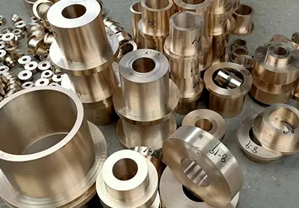
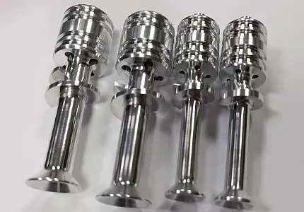
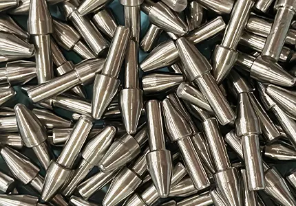
The outside micrometer is the most commonly used type, applied to external dimensions such as shafts, pins, and stepped diameters. It defines the baseline of dimensional verification in CNC turning.
The inside micrometer is used for bore and housing measurement, where internal diameter control is critical for fits such as H7/g6 clearance systems.
The depth micrometer is designed for stepped surfaces and groove depths, commonly found in mold bases and precision fixtures.
The thread micrometer is a specialized tool used to measure pitch diameter, which is critical in threaded connections where functional engagement depends on flank geometry rather than outer diameter.
The digital micrometer integrates electronic output, enabling direct data transfer into SPC (Statistical Process Control) systems. This is increasingly used in modern smart factories for traceable quality control.
A key engineering principle applies here: choosing the wrong micrometer type leads to incorrect data, even if the instrument itself is highly accurate.
12. Micrometer vs Other Precision Tools (Engineering Decision Table)
In CNC inspection systems, different measurement tools serve different decision layers.
Calipers are optimized for speed and general dimensional checking. They are suitable for non-critical features but lack the resolution needed for tight tolerance verification.
Micrometers operate as the precision verification layer, where dimensional compliance is confirmed within micron-level tolerances. They are slower than calipers but significantly more reliable for engineering decisions.
Gauge blocks function as calibration references. They are not production tools but are used to ensure that measuring instruments maintain traceability to national or ISO standards.
Coordinate Measuring Machines (CMMs) provide full geometric validation, including GD&T features such as flatness, perpendicularity, and true position. However, they are slower and typically used in laboratory or high-value inspection environments.
Engineering Positioning Summary
| Tool | Role in CNC Inspection | Strength |
|---|---|---|
| Caliper | Rapid dimensional check | Speed |
| Micrometer | Precision verification | Accuracy + repeatability |
| Gauge blocks | Calibration standard | Traceability |
| CMM | Full geometry validation | Comprehensive analysis |
In practical CNC decision-making, the micrometer occupies a unique position as the fastest precision decision tool in shop-floor inspection, balancing accuracy and operational speed better than laboratory systems or general-purpose tools.
![]()
Where:
- δ\delta = deformation
- FF = applied force
- LL = structural length
- AA = cross-sectional area
- EE = Young’s modulus
As the frame length decreases, deformation reduces, improving measurement consistency.
Practical CNC Engineering Logic
In real shop-floor environments, machinists rarely choose a “large range” micrometer unless necessary. The reasoning is practical rather than theoretical:
- Smaller range → higher frame stiffness
- Higher stiffness → lower deflection under ratchet force
- Lower deflection → improved measurement stability
This is why precision shops often maintain multiple micrometers (0–25 mm, 25–50 mm, etc.) instead of relying on a single wide-range tool.
The trade-off is clear: measurement range is sacrificed to gain structural precision stability.
15. Applications in High-Precision Industries
Micrometers are foundational in industries where dimensional variation directly affects functional safety and system reliability.
In aerospace manufacturing, components such as turbine shafts and actuator assemblies often require tolerances in the range of ±5–10 μm, where micrometer verification is essential for airworthiness compliance.
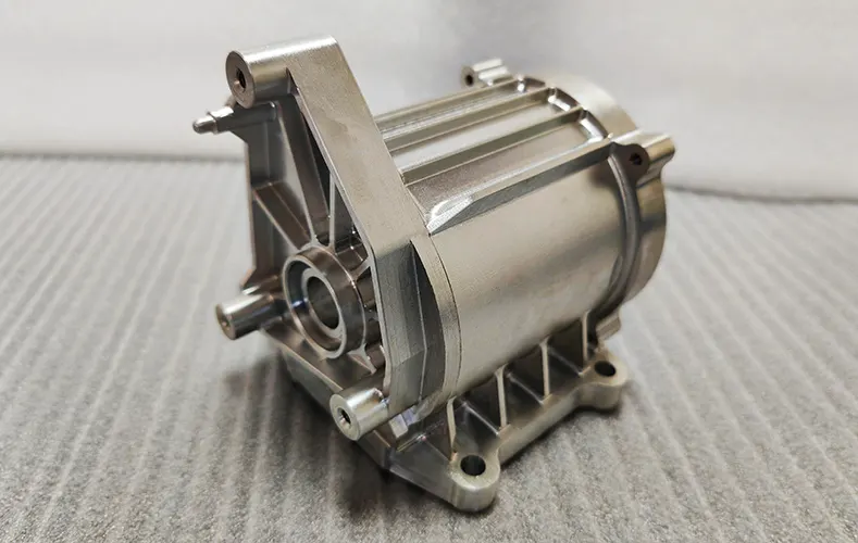
In automotive engineering, engine components such as crankshaft journals and piston pins depend on micrometer-controlled fits to maintain lubrication films and reduce friction losses.
Medical device manufacturing requires even stricter dimensional control. Surgical implants and precision instruments must maintain sub-10 μm consistency to ensure biological compatibility and mechanical reliability.
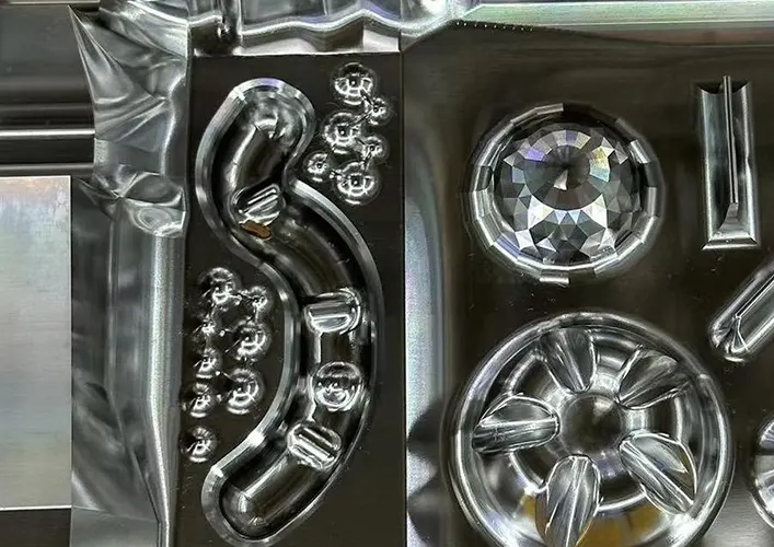
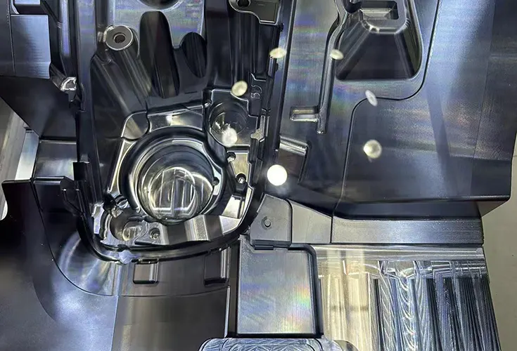
Precision mold and tooling industries rely heavily on micrometers to ensure cavity alignment, wear compensation, and repeatable injection molding quality across thousands of cycles.
In CNC prototyping, micrometers serve as a validation bridge between design intent and manufacturability, ensuring early-stage dimensional feasibility before scaling production.
16. Best Practices from CNC Professionals
Industrial metrology reliability depends heavily on disciplined measurement behavior rather than instrument capability alone.
One of the most critical practices is the consistent use of the ratchet mechanism. Manual force application introduces variability that can easily exceed several microns due to elastic deformation of both tool and workpiece.
Temperature control is another essential factor. Industry standards, including ISO 1, define 20°C as the reference temperature for dimensional measurement. Even small deviations introduce measurable expansion effects in metallic components.
Repeated measurements are standard practice in high-precision environments. Taking multiple readings reduces random error and improves statistical confidence in the result.
Clean measuring surfaces are equally critical. Even microscopic debris can create false readings due to surface interference, especially in high-tolerance fits.
Finally, operator consistency plays a major role. Variations in technique between machinists can introduce measurable differences, which is why standardized inspection procedures are enforced in production systems.
17. Key Insight: “Micrometer Is Not a Tool, It Is a Decision System”
In advanced manufacturing systems, inspection is not a post-process activity—it is an integrated part of production control.
A micrometer does not simply measure dimensions; it converts physical geometry into engineering decisions. Each reading determines whether a part continues through production, is reworked, or is scrapped.
This creates a direct linkage between machining, quality control, and customer acceptance. The micrometer becomes a feedback node in the manufacturing loop, enabling:
- Early detection of process drift
- Reduction of cumulative scrap rates
- Cost control through preventive correction
- Traceability in quality assurance systems
From a systems engineering perspective, the micrometer acts as a low-cost, high-precision decision interface between production output and engineering specification compliance.
18. Conclusion: Precision Defines Manufacturing Quality
CNC machining is ultimately not defined by cutting capability, but by controlled dimensional variation. The micrometer plays a central role in this control system by translating microscopic deviations into measurable engineering data.
Across all stages—from first article inspection to final validation—the micrometer ensures that manufacturing output remains aligned with design intent within micron-level tolerances.
Mastering its use is not just a technical skill; it is a core competency in precision manufacturing engineering. As tolerances tighten across aerospace, automotive, and medical industries, the importance of reliable micrometer-based inspection continues to grow.
In modern production systems, the principle remains consistent: small tools govern large outcomes.
References
- ISO 1: Geometrical Product Specifications — Standard Reference Temperature (20°C)
- ISO 3611: Micrometers for External Measurements
- JCGM 100:2008 (GUM) Guide to Measurement Uncertainty
- NIST Handbook of Dimensional Metrology
- Mitutoyo Technical Data Book: Precision Measuring Instruments
- ASM Handbook, Volume 16: Machining
- Groover, M.P., Fundamentals of Modern Manufacturing, Wiley
- Taylor, J.R., An Introduction to Error Analysis, University Science Books

")
")