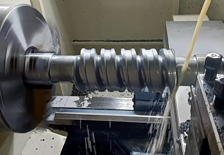
In the machining industry, when turning hard materials, many beginners will face a problem, that is, the turning inserts are easy to chipping, bringing great difficulties to the turning process.
To become a qualified machining operator, must understand and solve this problem, which is the key to improve the technical experience. It is also a way to improve work efficiency.
Here we analyze the situation of intermittent turning leading to carbide insert chipping, the goal is to find the most ideal solution for our operators.
Analysis of carbide insert chipping
Chipping phenomenon
In actual machining, operators often turn holes with oil groove parts. Since these parts need to be press-fitted with shafts or bearings, the machining accuracy and surface roughness of the holes must meet certain requirements.
In order to reduce the wear of the hole, generally have a hole in the parts using high-quality carbon structural steel or alloy steel, will bring great difficulties to the turning process.
Because parts with holes need to fit shafts or bearings, it is essential to finish the holes to achieve a surface roughness of Ra ≤ 1.6 μm.
When selecting tools, engineers choose carbide inserts suitable for finishing.
Although these inserts are wear-resistant, they lack impact resistance, so even slight vibration or impact can easily cause edge chipping;
While roughing carbide inserts are impact resistant but not wear-resistant, can not guarantee the dimensional accuracy and surface roughness of the hole.
When processing hard materials, the finishing back draft is generally less than 0.5 mm. During intermittent turning, the insert’s oil groove area often chips due to impact.
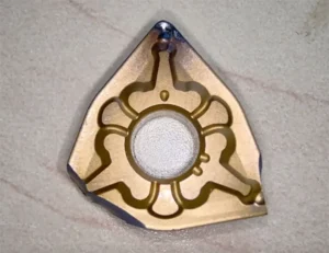
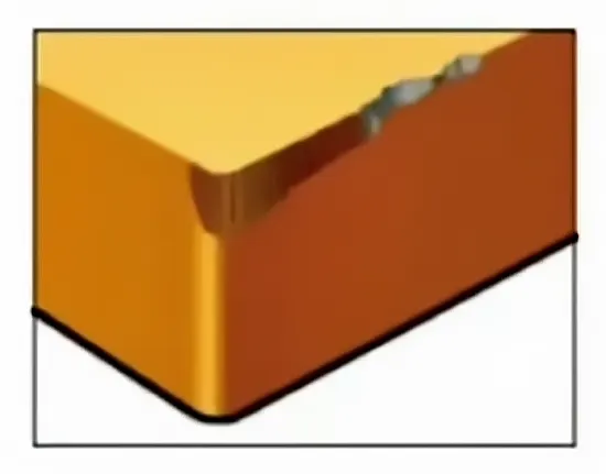
Blade breakage typically occurs at the blade tip and cutting edge, causing the tool to fail and preventing continued turning.
The chipping of the insert tip is shown in Fig. 1, and the chipping of the cutting edge of the insert is shown in Fig. 2.
Analysis of causes of insert chipping
Carbide inserts in the case of normal turning is a continuous cutting process, the blade whether there is a chipoma wear, plastic deformation wear or crescent pit wear, resulting in wear will have a process.
Intermittent turning causes sudden impacts that lead to blade chipping during the cutting process.
Therefore, we must analyze the factors affecting cutting forces to find effective solutions for preventing blade chipping.
Cutting force has a greater impact on the factors analyzed as follows.
(1) Selection of Tool Main Deflection angle.
Among the tools used in turning, the main deflection angle of turning has a greater influence on the cutting forces.
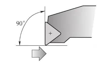
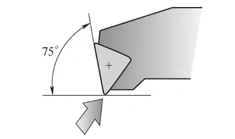
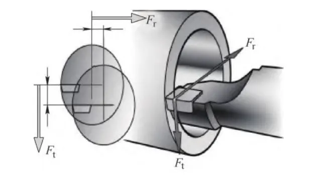
The 75° main offset tool generates a larger radial cutting force compared to the 90° tool. As a result, cutting vibration and tool deflection increase.
Figure 3 shows the force direction for the 90° main offset tool, while Figure 4 illustrates the force direction for the 75° tool.
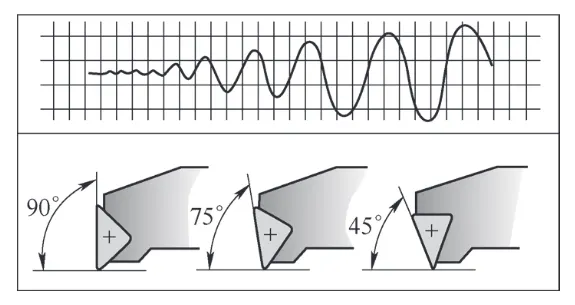
Figure 5 compares the turning vibration curves for tools with main offset angles of 90°, 75°, and 45°.
Although the 75° main offset tool generates a larger radial cutting force than the 90° tool, their contact with the workpiece differs during turning.
When the tool starts cutting or encounters a fault, the 90° tool’s cutting edge and tip contact the workpiece simultaneously.
In contrast, the 75° tool’s cutting edge contacts the workpiece first, followed by the tip. This means the cutting edge absorbs the initial impact, and the tip receives the impact afterward during the turning process.
Figure 5 shows that the turning vibration amplitude of the 45° main offset tool is larger than that of the 75° and 90° main offset tools. Therefore, only the 75° and 90° tools are compared.
Although the tip of the 75° main offset tool experiences impact during cutting, which can cause chipping, its tip condition remains better than that of the 90° tool.
For intermittent turning, choosing the 75° main offset tool is more desirable.
To solve the turning vibration caused by large radial cutting force, engineers adjust the cutting parameters.
(2) Correctly Install the Tool
Although carbide insert manufacturers offer many standard front and rear angle options, selecting angles based on whether the operation is roughing or finishing is essential.
However, the tool installation process has an even greater impact on the effective front and rear angles of the insert
When machining internal holes, the height of the center of the mounted turning tool is too high will cause the actual back angle of the tool to increase, thus causing chipping;
If operators install the lathe tool too low, the actual relief angle decreases.
This causes friction between the insert’s rear face and the workpiece, which can lead to oversized machining and increased risk of vibration. Figure 6 illustrates how changes in tool center height affect performance.
Therefore, operators must install cutting tools according to standard height requirements.
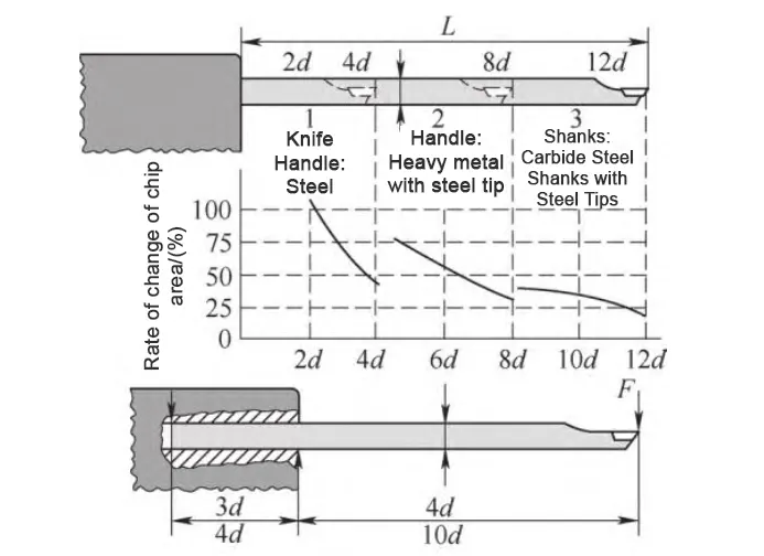
The clamping length of the internal hole turning tool should be ensured to be at least 3d while ensuring good clamping and normal cutting.
When machining a 10d hole, engineers should ensure a minimum clamping length of 4d. Figure 7 illustrates the proper clamping length of the turning tool.
During intermittent turning, in addition to maintaining the effective length of the tool bar, they should also maximize the clamping length to enhance stability.
(3) Improvement of the Tip and Cutting Edge
The material of the insert and the angles of the front and back of the insert remain unchanged by the finishing method.
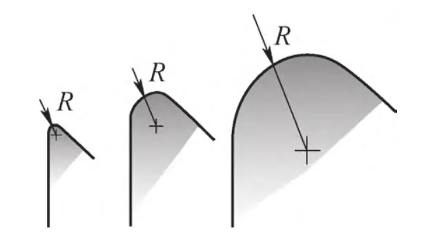
To avoid chipping during intermittent turning, engineers choose a larger tip angle and increase the tip arc radius, as long as the workpiece and system rigidity allow.
A larger tip arc radius enables the tool tip to better withstand the impact of intermittent cutting. Figure 8 shows the enlarged tip arc radius.
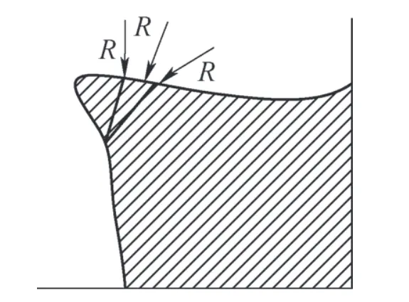
When the cutting edge of the insert lacks negative chamfering or does not have a properly sized chamfer, it becomes vulnerable under the impact force of intermittent turning.
The edge is subjected to tensile stress, which can easily lead to chipping. Figure 9 shows the cutting edge without negative chamfering, illustrating this issue.
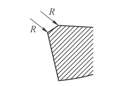
Engineers apply negative chamfering to the cutting edge of the insert so that the edge experiences compressive stress. This approach helps prevent chipping along the insert edge.
As shown in Figure 10, the negative chamfering of the cutting edge effectively addresses the chipping problem at the tip and edge of carbide inserts caused by intermittent turning.
(4) Optimization of Cutting Tools
While addressing the chipping problem at the tip and edge of the carbide insert, engineers may encounter turning vibrations, which can compromise the machining quality.
These vibrations may also cause additional chipping. To resolve this, they need to further optimize the cutting parameters to improve overall machining performance.
These vibrations can also lead to additional chipping. To address this, they must further optimize the cutting parameters to enhance machining quality.
The relationship between the tip radius and back draft will affect the vibration trend, the relationship between the tip radius, back draft and cutting force is shown in Figure 11.
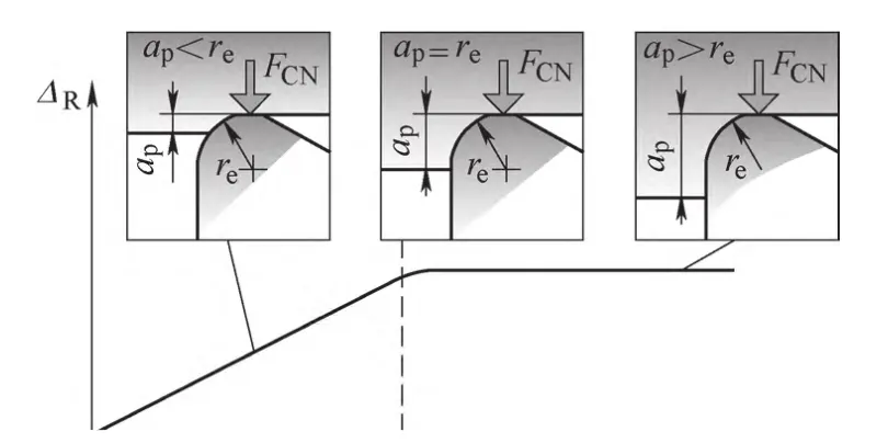
When the backstroke <tip radius, the radial cutting force increases;
When the amount of backstroke = tip radius, the radial cutting force tends to stabilize;
Back draft > tip radius, the radial cutting force is completely stabilized.
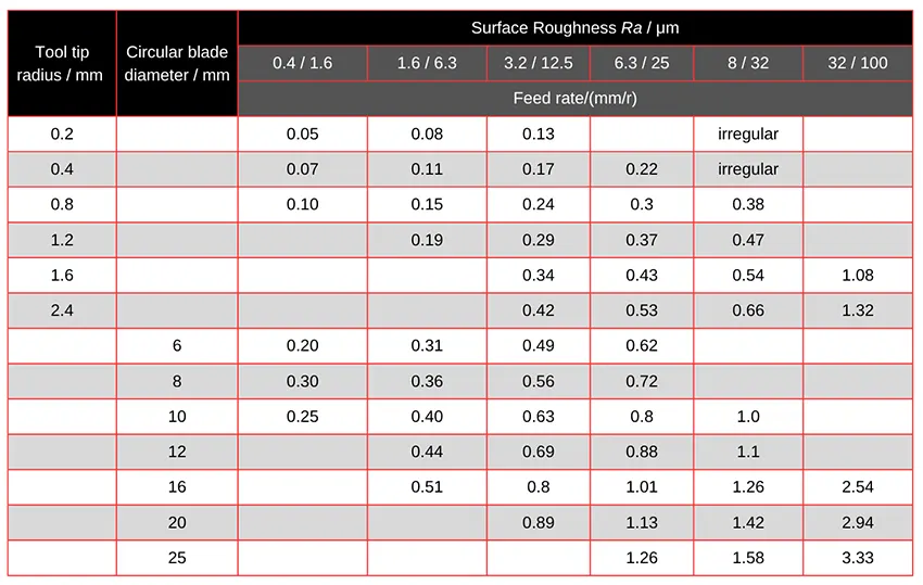
When selecting the tip radius, engineers ensure that the radius is slightly smaller than the back draft.
There is also a specific relationship between the tip radius, feed rate, and surface roughness. Table 1 provides the feed selection guidelines based on these factors.
As for cutting speed, they choose it according to general semi-finishing turning standards.
Specific case
The workpiece being machined is 80mm diameter bushing with oil groove, material 40 CrV, machining accuracy 7, surface roughness value Ra = 1.6μm.
To meet the technical requirements of product processing and address the issue of carbide insert chipping caused by intermittent turning, engineers conducted analysis and research.
Based on their findings, they outlined the specific optimization measures described below.
The tool, with a main deflection angle of 75°, is selected for cutting. The insert model is SCMT120404, brand GC4225, with a tip radius of 0.4mm and a negative chamfer of 0.3 mm on the insert edge.
The cutting parameters are as follows: cutting speed v = 90 m/min, feed f = 0.07mm/r, and back-eating amount ap = 0.4mm.
The cutting speed v=90m/min, the feed f=0.07mm/r, the back draft ap =0.4mm. A 4 mm and a blade edge negative chamfer of 0.3 mm cannot be satisfied at the same time; therefore, they need to be manually sharpened.
Once the tool and cutting parameters are formulated, it is also necessary to visit the production site for trial cutting to adjust and verify the parameters.
In actual production, the above optimization method withstood the test of intermittent turning impact, and the turning effect is more satisfactory.
Conclusion
In machining, engineers encountered the problem of intermittent turning caused by the collapse of carbide inserts, which made turning operations impossible. To solve this issue, they carried out research and analysis.
They focused on the cutting forces acting on the metal, the cutting angle of the tool, and the shape of the cutting edge. Based on these factors, they selected and improved the cutting tool design.
After optimizing the tool, they further refined the cutting parameters to enhance performance.
In the production process, as long as the hardness of the processed parts material is below 50HRC alloy steel, this method can be used for processing.
FAQ
Why do carbide inserts chip during intermittent turning?
Carbide inserts chip during intermittent turning due to sudden impact forces when the tool engages and disengages the workpiece. These forces stress the insert’s tip and cutting edge, especially if it lacks impact resistance or is improperly installed.
How does intermittent turning affect tool life?
Intermittent turning causes rapid tool wear and frequent insert chipping, reducing overall tool life. The repeated impact disrupts cutting stability and often leads to early failure at the blade tip or cutting edge.
What tool angle is best for intermittent turning?
A 75° main deflection angle is generally preferred for intermittent turning. It offers a balance between strength and impact resistance, with the cutting edge absorbing the initial force and protecting the tool tip from direct shock.
How can I prevent chipping in carbide inserts?
To prevent chipping, use inserts with negative chamfering, select a larger tip arc radius, choose the correct tool deflection angle (e.g., 75°), and ensure proper clamping and tool installation height. Optimizing cutting parameters also plays a crucial role.
What role does tool installation play in insert chipping?
Improper installation height can alter the relief and rake angles, increasing friction or weakening the cutting edge. Installing the tool too high or too low can lead to poor surface finish and increase the risk of chipping and vibration.
What are the ideal cutting parameters to avoid chipping?
Ideal parameters for hard material intermittent turning include a cutting speed of 90 m/min, a feed rate of 0.07 mm/r, and a back draft of 0.4 mm. These values must be fine-tuned based on insert geometry and material hardness.
How does tip radius affect cutting performance?
A slightly smaller tip radius than the back draft helps stabilize radial cutting force and reduces vibration. A larger tip radius improves the tool's ability to absorb impact, but must be balanced with feed rate and surface finish requirements.
Why is negative chamfering important for carbide inserts?
Negative chamfering places the insert edge under compressive stress, which significantly improves its resistance to chipping during impact. It prevents edge breakage under the harsh conditions of intermittent cutting.
What insert type is best for finishing hard materials?
For finishing hard materials with surface roughness requirements (e.g., Ra ≤ 1.6 μm), use wear-resistant carbide inserts like SCMT120404 with a suitable chamfer and tip radius. However, these inserts should be used in stable conditions due to their low impact resistance.
Can I use the same insert for roughing and finishing?
No, roughing inserts are impact-resistant but not wear-resistant, making them unsuitable for achieving tight tolerances and smooth surfaces. Finishing inserts provide the required accuracy and surface quality but are more prone to chipping under impact.

