CNC machine tools are known as the modern manufacturing industry’s “workhorse”, its technological sophistication is a measure of the manufacturing technology level and the core of the industrial base of the logo, in the global manufacturing industry to digitalization, intelligent transformation trend, CNC machine tools in the field of high-end applications are increasingly widespread.
The dimensional accuracy of CNC machine tool manufacturing directly affects the product performance and reliability, especially in the field of aviation, automobile, precision instruments, etc., the manufacturing accuracy of the final quality of the product is critical.
Generally speaking, the accuracy of the machine tool determines the highest precision you can achieve in product manufacturing, so this is an issue of great concern to many machine tool manufacturers and users.
However, there are many factors affecting accuracy, and the methods of controlling them are very different.
This is a practitioner to say, this is not a small challenge, the following analysis of these factors one by one, so that everyone understands the current situation of the industry face in this regard.
Cutting dimensional accuracy factors affecting
In the actual application of CNC machine tools in metal cutting processing, dimensional accuracy is influenced by multiple factors.
These include the machine tool body structure, the tool and workpiece system, cutting parameters, and environmental conditions.
Together, these multidimensional factors comprehensively impact the final manufacturing accuracy.
Influence of the body structure of the machine tool
The impact of the body structure of the machine tool mainly includes.
First, the impact of geometric errors must be considered.
The main geometric errors in CNC machine tools include guide rail errors, spindle errors, and screw errors.
Guide rail errors such as straightness and parallelism tend to worsen over time due to wear and lubrication issues.
Spindle radial and axial runout can occur because of bearing wear and cutting forces, causing processing inaccuracies.
Ball screw pitch errors and backlash also contribute to positioning accuracy errors.
Together, these geometric errors significantly affect the overall machining precision.
The second factor is the impact of thermal deformation error.
Since most parts of CNC machine tools are made of metal materials, structures like the machine bed and column are susceptible to thermal deformation.
This deformation occurs due to temperature gradients generated during operation and from the environment.
As a result, the geometric accuracy of the machine tool experiences drift.
For example, a gantry machining center in the environmental temperature change 10 ℃, Z-axis thermal elongation can reach 0.03 mm.
In addition, heat generated during the cutting process is conducted through the tool, workpiece, and machine tool.
This heat causes local thermal deformation of the manufacturing structure. As a result, machining accuracy declines.

Tool and workpiece system error effects
Tool error is mainly caused by tool wear, installation errors, and other factors.
During long-term mass production, tools can develop edge blunting and face wear.
They may also experience coating flaking, micro-cracks, and other microscopic damage, which lead to actual position errors during machining.
Additionally, misalignment in coaxiality between the tool and tool shank, as well as between the workpiece and machine tool, can cause local thermal deformation.
This deformation results in a decline in machining accuracy.
Tool and shank coaxial deviation, inadequate clamping force may also cause microscopic vibration, resulting in reduced machining accuracy.
The main source of workpiece error comes from clamping deformation of the raw material.
This is especially true for thin-walled parts, slender shafts, and other components prone to elastic deformation under clamping force.
Such deformation leads to a decline in machining quality.
Additionally, machining accuracy can be affected by the hardness of the workpiece material and differences in its elastic modulus.
Cutting parameters and process error effects
Cutting parameter setting on processing quality has a great impact, for example, cutting speed is too high easily triggered by increased tool wear, speed is too low will lead to the formation of chip tumors, may produce processing manufacturing errors.
Different choices of feed and depth of cut will cause the impact of machining efficiency and surface quality.
For example, too large a feed or depth of cut can cause an increase in surface roughness.
In addition, when processing parts with complex surfaces or intricate structures, the design of the machining process also impacts manufacturing quality.
For example, sudden changes in the tool trajectory while machining complex surfaces can cause shock vibrations.
These vibrations may lead to a decline in dimensional accuracy.
Influence of the environment and external interference
Environment and external interference effects mainly include:
1) external vibration sources, such as neighboring equipment operation, ground vibration caused by vibration of CNC machine tools.
2) the impact of internal vibration, such as motor vibration, gear meshing vibration and other adverse effects, gear drive system meshing frequency and machine tool intrinsic frequency close to the resonance may be triggered; 3) electromagnetic interference effects, such as neighboring equipment operation, ground vibration caused by CNC machine tool vibration.
3) electromagnetic interference, resulting in CNC machine tools produce servo motor control signal distortion, positioning errors and other issues.

Control techniques and methods
Application of error compensation techniques
Geometric error compensation
Geometric error compensation is used to solve the manufacturing and assembling deviation of machine tool guideway, spindle and other components. At the present stage, the geometric error is solved by applying the calibration technology of laser interferometer.
Renishaw XL-80 and other laser interferometers can achieve measurement resolutions as fine as 0.01 μm for machine tool axes, including straightness and perpendicularity errors.
The laser interferometer is fixed on the machine tool table, while a reflector is installed on the moving part to collect measurement data.
As the interferometer moves, it records error values in real time at every millimeter position.
These data points are then used to establish an error model through methods such as polynomial fitting or neural networks.
Based on the resulting error model, instruction positions are corrected using inverse kinematics.
This enables real-time compensation, significantly improving machining accuracy.
Thermal error compensation
Thermal error compensation is used to solve the problem of dimensional accuracy drift of thermal deformation of machine tools.
Thermocouple sensors are arranged in key parts of machine tools, such as spindles and beds, to collect temperature data.
This data is combined with Finite Element Analysis (FEA) technology to establish a thermal-force coupling model.
The model enables scientific prediction of thermal deformation in the machine tool components.
The deformation amount (ΔL) can be calculated using the formula:
ΔL=11.7×10⁻⁶×L0×ΔT+0.0002×ΔT2
where ΔL is the amount of deformation; L0 is the initial length and ΔT is the temperature change.
Application of intelligent control strategy
With the deep development of intelligent manufacturing technology, intelligent control technology can realize adaptive adjustment and predictive optimization for CNC machine tools, thus improving the stability of the machining process.
Adaptive Control
Adaptive control mainly focuses on monitoring the cutting force during the tool machining process.
By installing advanced force sensors—such as the Kistler 9257B—on the tool shank or spindle, the system can collect cutting force signals in real time.
When the system detects that the cutting force exceeds a preset threshold, it automatically reduces the feed rate or depth of cut through active decision-making control
In addition, at the software level, by applying Particle Swarm Optimization (PSO) or Genetic Algorithm (GA), the adaptive control can be extended to optimize the cutting parameters according to the cutting force, tool life and other objectives.
Fuzzy control and neural network prediction
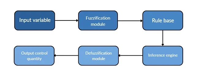
Fuzzy control realizes the control of complex system by establishing the fuzzy rule base of cutting force, vibration signal and tool wear state, and transforming the operator’s experience into fuzzy rules, and its core control logic is shown in Fig. 1.
The core control logic is shown in Fig. 1. Key parameters such as machining error, error change rate, spindle speed, and feed rate are set as input variables.
These precise input variables are then converted into fuzzy linguistic variables. Using a rule base and inference engine, the system matches control variable rules with fuzzy outputs.
Next, a defuzzification module converts the fuzzy outputs back into precise control quantities.
This process enables effective control of the machine tool’s actuator.
Neural network prediction can be used to predict key factors such as machining error, tool wear or machining time by simulating the work of neurons in the human brain and learning the mapping relationship between input and output.
The principle of neural network prediction is as follows.
[Input layer] → [Hidden layer 1] → [Hidden layer 2] → …→ [Output layer]

By using historical processing data—such as spindle speed, feed speed, cutting force, tool wear, and workpiece material characteristics—as inputs to a neural network, accurate predictions can be made.
The neural network processes the input data through weighted summations and nonlinear activation functions like ReLU and Sigmoid in its hidden layers to extract relevant features.
This enables precise prediction of machining errors and remaining tool life.
Based on these predictions, the system can then guide corrections in the machining process to improve accuracy and efficiency.
The system can be guided to compensate for the machining process and realize the predictive replacement of tool wear.
Tool condition monitoring technology
Acoustic emission and vibration signal monitoring
Acoustic emission (AE) monitoring for tool condition primarily relies on AE sensors to capture high-frequency signals generated during the cutting process. These signals are analyzed using wavelet transform to extract characteristic frequencies.
When tool wear intensifies, the AE sensor detects a noticeable increase in signal energy. In response, the machining state can be adjusted—such as by modifying the feed rate—to reduce tool wear errors.
In parallel, vibration signal monitoring involves installing acceleration sensors on the tool shank or spindle to observe the vibration spectrum. When the dominant vibration frequency deviates from the normal range, it indicates an abnormal tool condition.
The system then provides prompts or takes corrective action based on the vibration data to maintain machining stability and tool integrity.
Vibration signal monitoring involves installing acceleration sensors on the tool shank or spindle to track the vibration spectrum during machining.
When the vibration frequency deviates from the normal range, it indicates an abnormal condition of the tool.
In response, the system can issue prompts or use fuzzy control algorithms to optimize the machining strategy accordingly.
Online monitoring
Tool condition online monitoring technology is a multi-signal fusion monitoring system. It works by collecting real-time signals such as tool vibration, acoustic emission, cutting force, current, and temperature during machining.
These signals are then analyzed using advanced data processing algorithms to assess tool conditions in real time. The system can detect wear, breakage, chipping, and other issues, providing early warnings to prevent sudden tool failure.
This helps avoid potential workpiece scrap or machine tool damage caused by unexpected tool breakage. Additionally, it enables the optimization of tool usage strategies.
Based on the real-time condition of the tool, the system can dynamically adjust cutting parameters. This avoids the risk of “working with disease” (i.e., continuing machining with a worn tool) and extends the tool’s service life.
Automatic tool change
To reduce tool wear and the resulting decline in machining accuracy, a systematic tool monitoring and replacement program should be established.
On one hand, technologies such as vibration sensors, acoustic emission sensors, force sensors, and machine vision can be used to monitor tool wear in real time.
These monitoring systems can be combined with machine learning algorithms—such as neural networks and support vector machines—or with statistical analysis methods.
By doing so, a tool wear prediction model can be developed to estimate both the current wear level and the remaining life of the tool.
This predictive approach allows for timely tool replacement, ensuring consistent machining accuracy and extending overall tool efficiency.
On the other hand, based on the results of tool wear monitoring, the system can automatically trigger a tool change when wear reaches a preset threshold.
It uses chain-type, disk-type, or turret-type tool changers to ensure fast and accurate tool replacement. After the tool is changed, precision measuring instruments are used to check the positioning accuracy of the new tool.
This ensures that the machining process remains accurate even after the tool has been replaced.
Cutting parameters optimization
The reasonableness of cutting parameters—such as speed, feed, and depth of cut—directly impacts the dimensional accuracy and surface quality in processing and manufacturing.
To enhance this, AI-driven intelligent analysis technologies can be introduced into the CNC machining process. When combined with cutting process simulation tools like DEFORM-3D or ABAQUS, these technologies can help evaluate and optimize machining parameters.
Through simulation and analysis, it becomes possible to correct settings for speed, feed, and depth of cut. Additionally, dynamic adjustment of these parameters during machining can be achieved.
Such improvements are beneficial for optimizing the cutting process. They help reduce cutting force fluctuations, enhance process stability, and ultimately ensure greater accuracy in manufacturing.
Adjustment is conducive to improving the cutting force, temperature field and residual stress on the machining accuracy.
In addition, the software should be further optimized by improving the rationality of the machining tool’s running path. This includes using NURBS curve fitting for the tool trajectory to achieve smoother movement.
A smooth path helps avoid sudden changes in trajectory, which can cause vibrations and lead to degraded machining quality. Furthermore, by applying topology optimization to the design of the tool path, it is possible to reduce the peak cutting forces.
This reduction in cutting force helps prevent deformation of the workpiece during machining.
Conclusion
With the booming development of the manufacturing industry, CNC machine tools have become the core equipment of modern machining. Their ability to control metal cutting dimensional accuracy is directly related to the quality of the processed parts.
In addition, this control level also affects the performance and productivity of the entire manufacturing process. Ultimately, it plays a crucial role in determining the overall competitiveness of the manufacturing industry.
Factors Affecting Dimensional Accuracy
By analyzing the precision of the machine itself, tool wear, geometric parameters, workpiece materials, and other factors that affect the CNC machine tool metal cutting process, it becomes evident that these elements have a significant impact on dimensional accuracy.
This highlights the importance of addressing these influencing factors. It also emphasizes that improving them is an effective way to enhance the accuracy of machining and manufacturing
Optimizing the Machining Process
At present, in addition to the content of this paper, attention should also be paid to the processing of high-precision, thin-walled parts and other special components. It is important to focus on process improvements for these complex parts.
Moreover, the integration of real-time monitoring, simulation, and analysis technologies should be considered. These tools can help optimize the manufacturing process, refine cutting parameters, and improve the machining path.
Together, these efforts aim to achieve optimal control of the machining process. Ultimately, this will provide strong support for the high-quality development of the manufacturing industry.
What is dimensional accuracy in CNC machine tools, and why is it important?
Dimensional accuracy in CNC machine tools refers to the precision with which a part matches its intended measurements. It is crucial because it directly affects product performance and reliability, especially in industries like aerospace, automotive, and precision instrumentation.
How does the machine tool’s body structure influence dimensional accuracy?
The body structure of a CNC machine tool—especially geometric errors in guide rails, spindles, and screws—greatly impacts dimensional accuracy. Over time, wear and thermal deformation can introduce deviations that reduce machining precision.
What role do thermal deformations play in reducing CNC machining accuracy?
Thermal deformation occurs due to temperature gradients during machine operation. Components like beds and spindles expand or contract, causing geometric shifts that can lead to up to 0.03 mm deviation in Z-axis dimensions, affecting overall accuracy.
How do tool wear and workpiece clamping affect CNC dimensional accuracy?
Tool wear such as edge blunting or coating flaking causes positioning errors during cutting. Similarly, improper clamping of flexible workpieces can lead to elastic deformation, resulting in reduced machining accuracy.
What are the effects of cutting parameters on CNC machining precision?
Incorrect cutting parameters—such as excessive speed or depth of cut—can increase tool wear, generate chip buildup, and cause vibration. These conditions negatively impact dimensional accuracy and surface finish.
How does the machining environment affect CNC dimensional accuracy?
Environmental factors like external vibrations, internal resonance, and electromagnetic interference can distort servo motor signals and trigger machining errors. Stable operating conditions are essential for high precision.
What technologies are used to compensate for geometric and thermal errors in CNC machining?
Advanced error compensation methods include laser interferometers for geometric calibration and thermocouple sensors for thermal error modeling. These technologies enable real-time corrections and enhance dimensional accuracy.
How does intelligent control improve CNC machining precision?
Intelligent control systems—using AI algorithms like PSO, GA, fuzzy logic, and neural networks—monitor cutting forces and tool wear to dynamically adjust machining parameters, improving stability and accuracy.
What is the function of online tool condition monitoring in CNC machining?
Online monitoring systems use signals like acoustic emission, vibration, and temperature to assess tool health in real time. They prevent unexpected tool failure and ensure consistent dimensional accuracy.
How does optimizing cutting parameters and tool paths enhance CNC machining accuracy?
Optimized cutting parameters and smooth tool paths—achieved through simulation software and NURBS curve fitting—reduce vibration, control cutting forces, and prevent workpiece deformation, all of which improve dimensional accuracy.

