Table of Contents
The turning tool is the most commonly used cutting tool for machining workpieces. The selection of turning tool geometric angles directly affects the dimensional accuracy, surface roughness, and cutting efficiency of the workpiece.
For novice turning students, the types, composition, and applications of turning tools are relatively easy to understand and master.
Why Turning Tool Angles Matter?
However, grasping the influence of turning tool geometric angles on cutting operations presents greater challenges, thereby complicating the selection of angles during tool sharpening and cutting processes.
Tool geometric angles are critical parameters that determine the geometric shape of the cutting portion of a tool and ensure its cutting performance.
We define the geometric angles of a turning tool as the angles formed between the tool face, tool edge, and reference plane system.
Basic and Derived Angles in Turning Tools
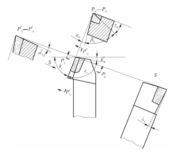
The cutting portion of a turning tool has six independent basic angles (as shown in Figure 1):
Central rake angle Kr, secondary rake angle Kr′, front angle γo, main clearance angle αo, secondary clearance angle αo′, and edge inclination angle λs; plus two derived angles: tool tip angle εr and wedge angle βo.
These geometric angles have a significant impact on the entire turning process, with the central rake angle Kr and front angle γo having the most prominent effects.
To ensure processing quality, improve efficiency, and reduce costs, this paper analyzes the influence of the central rake angle Kr and front angle γo on cutting force, cutting heat, and tool durability, and establishes general principles for determining scientific turning tool geometric angles.
Auxiliary planes for measuring tool cutting angles
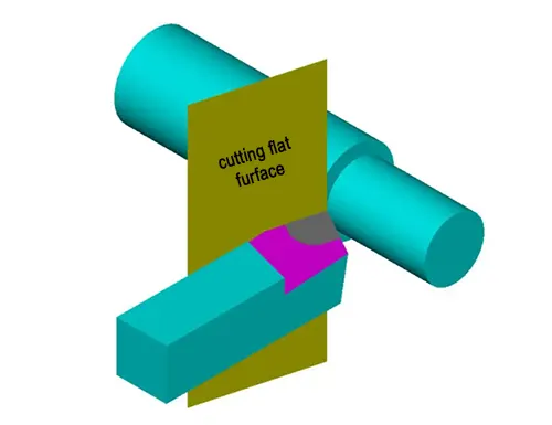
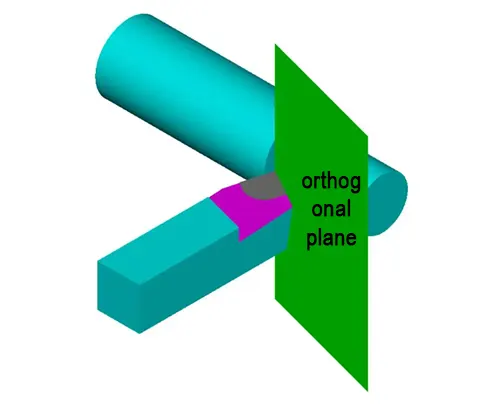
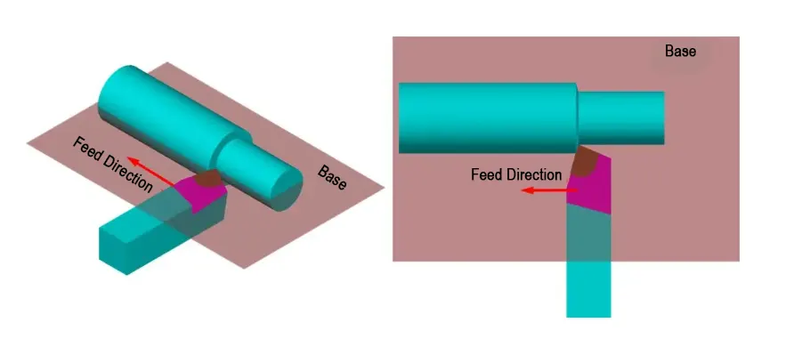
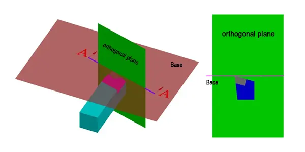
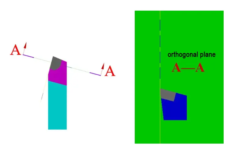
We determine and measure the geometric angles of a tool by selecting three auxiliary planes as reference planes: the cutting plane, the base plane, and the orthogonal plane.
1) Cutting plane — a plane that intersects the leading cutting edge at a selected point and is perpendicular to the bottom plane of the tool shank.
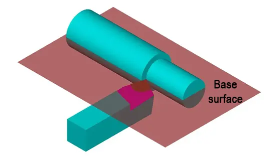
2) Base plane — a plane that passes through the leading cutting edge at a selected point and is parallel to the bottom plane of the tool shank.
3) Orthogonal plane — a plane that is perpendicular to both the cutting plane and the base plane.
These three coordinate planes are mutually perpendicular, forming a spatial rectangular coordinate system.
Influence of Tool Geometric Angles on Cutting Forces
During cutting operations, we refer to the resistance that the workpiece material generates against the tool’s cutting action as cutting force.
Two main factors generate cutting force: deformation of the workpiece material and chip formation, and friction between the workpiece and the tool.
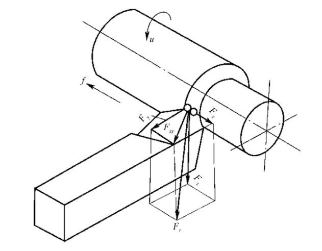
Because measuring the magnitude and direction of cutting force is difficult, we typically decompose it into three mutually perpendicular component forces for analysis, calculation, and design purposes:
The primary cutting force Fc (Fz), the back force Fp (commonly referred to as the radial force Fy), and the feed force Ff (widely referred to as the axial force Fx).
Typically, the primary cutting force is the most significant component and serves as the primary basis for determining the motor power of the machine tool, verifying the strength and rigidity of the machine tool, and calculating the strength of the cutting insert.
During turning, a huge primary cutting force can cause tool deflection or tool breakage.
The back force is the primary factor causing vibration and workpiece bending deformation during cutting.
The feed force is the basis for verifying the strength and rigidity of the main components of the machine tool feed system.
Influence of the Central Rake Angle Kr on Cutting Forces
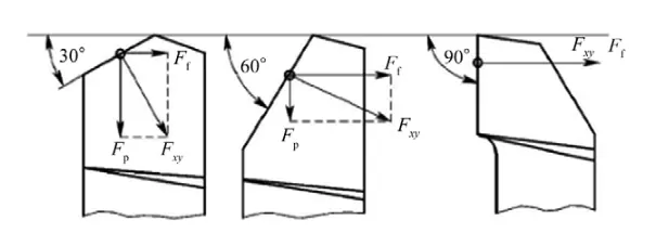
The central rake angle Kr primarily affects the proportional distribution of the back force Fp and feed force Ff.
Changes in the central rake angle Kr alter the direction of the cutting component force Fxy and the shape of the cutting area, thereby causing the cutting forces to change accordingly.
According to the cutting force decomposition formula: Fp = Fxycos Kr; Ff = Fx y sinKr, it can be seen that an increase in the central rake angle Kr reduces the back force and increases the feed force, which helps to minimize workpiece deformation and system vibration.
In actual cutting operations, larger main rake angle turning tools are often used to cut slender shaft-type parts to reduce the back force Fp, as shown in Figure 3.
Effect of front angle γo on cutting forces
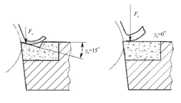
The front angle γo has the greatest influence on the main cutting force.
When the front angle γo increases, the tool becomes sharper, reducing the squeezing force on the workpiece and minimizing deformation of the cutting layer metal.
This effectively reduces friction between the chip and the front face, thereby decreasing the main cutting force, as shown in Figure 4.
Influence of Rear Angle αo on Cutting Force
The rear angle αo generally has a negligible influence on cutting force compared to the front angle γo.
When the front angle is the same, the cutting force decreases as the rear angle increases.
An increased rear angle sharpens the cutting edge, improves friction between the rear face and the machined surface, and enhances cutting performance.
However, a huge rear angle may reduce the cutting force.
The Effect of Tool Geometric Angles on Cutting Heat
Cutting heat is an essential physical phenomenon in the cutting process, directly affecting tool wear and life, influencing workpiece processing quality and surface accuracy, and limiting the increase in cutting speed.
Friction between the tool’s front face and the chip, as well as between the tool’s rear face and the workpiece, is one of the primary sources of cutting heat.
The chip, workpiece, tool, and surrounding medium dissipate the heat generated during cutting. Generally, the chip carries away most of the heat.
There are numerous factors influencing cutting heat, but this analysis focuses on the impact of turning tool geometric angles on cutting heat.
Influence of the Central Rake Angle Kr on Cutting Temperature
Under the same back cutting depth, reducing the central rake angle Kr increases the length of the cutting edge involved in cutting, increases the point angle, enhances the strength of the cutting edge, increases the heat dissipation area of the tool, and improves heat dissipation conditions, thereby reducing cutting temperature.
Conversely, increasing the central rake angle Kr raises the cutting temperature.
Therefore, when the process system has good rigidity, we can use a smaller central rake angle for cutting, which not only reduces the cutting temperature but also improves tool durability, as shown in Figure 5.
Figure 5: Effect of the central rake angle on tool heat dissipation performance
Effect of the front angle γo on cutting temperature
The size of the front angle γo directly affects deformation and friction during the cutting process, thereby significantly influencing cutting temperature.
Increasing the front angle reduces cutting deformation, facilitates chip evacuation, decreases friction between the chip and the front face, and lowers cutting temperature by approximately 9%.
However, a huge front angle deteriorates the tool’s heat dissipation performance, and the cutting temperature will not decrease further.
If we take the cutting temperature with a front angle of 10° as the base value 1, it becomes 1.08 at -10°;
At 18°, it is 0.85; and at 25°, it is 0.8. When the rake angle of the turning tool increases to approximately 15–20°, the reduced wedge angle of the tool worsens its heat dissipation conditions, and the cutting temperature does not change significantly.
Influence of Tool Geometry Angles on Tool Life
Tool life is the sum of the pure cutting time between two sharpenings of the tool, serving as a comprehensive indicator of the tool’s cutting performance.
Under the same cutting conditions, a higher tool life indicates that the tool’s geometry angles are more reasonable.
Influence of the Central Rake Angle Kr on Tool Durability
Reducing the main rake angle Kr and the secondary rake angle Kr′, and increasing the radius of the tool tip arc, can enhance tool tip strength, reduce cutting temperature, and thereby improve tool durability.
However, if we reduce the central rake angle and secondary rake angle excessively when the system lacks sufficient rigidity, problems can occur. In that case, it will increase the back force Fp and cause vibration, thereby affecting processing quality.
Effect of the front angle γo on tool durability
An appropriate increase in the front angle γo reduces cutting deformation and friction, thereby decreasing cutting force, lowering cutting temperature, and improving tool durability.
However, a huge front angle can worsen heat dissipation conditions, reduce strength, and cause tool damage, thereby decreasing tool durability.
The relationship between the front angle γo and tool durability follows a peak-shaped curve, with the highest durability at the peak value.
Of course, the optimal front angle value for achieving maximum durability varies depending on the cutting material.
Influence of Tool Angles on Chip Build-Up
Causes of Chip Build-Up
During machining, the squeezing and friction of the front face cause the underlying metal of the chip to form a stagnant layer due to slow flow, which simultaneously generates a large amount of cutting heat.
Under high temperature and pressure, some small particles on the chip melt and soften, adhering to the tip of the front face.
Due to work hardening, these particles form wedge-shaped structures with extremely high hardness, known as built-up edges.
When the built-up edge detaches due to vibration, impact, or friction, it gradually forms a new built-up edge.
The detachment and regrowth of the built-up edge cause local fluctuations in the cutting process, severely affecting the surface quality of the workpiece.
Influence of Tool Angles on Built-up Edge Formation
The formation of built-up edges is primarily caused by friction and compression between the chip and the rake face, which generates cutting heat, melts small particles, and forms wedge-shaped hardened structures.
Selecting an appropriate tool with geometric angles can effectively prevent or reduce the formation of built-up edges.
(1) Tool front angle γ0
Increasing the tool front angle reduces chip deformation, friction between the chip and the front face, cutting force, and cutting heat, thereby suppressing chip formation or reducing chip height.
(2) Tool rear angle α0
The rear angle reduces friction between the tool’s main rear face and the workpiece’s transition surface, as well as wear on the main rear face.
We adjust it in conjunction with the front angle to control the sharpness and strength of the cutting edge, directly affecting surface finish quality and tool durability.
Influence of Turning Tool Geometric Angles on the Rigidity of the Machining System
Machining System Rigidity
In turning operations, we refer to the entire machining process—including the lathe, fixture, workpiece, and turning tool—as the machining system.
The magnitude of force-induced deformation in the machining system depends on its ability to resist deformation, and the metric used to assess this ability is the machining system rigidity.
Under the influence of cutting forces, transmission forces, inertial forces, clamping forces, and gravitational forces, each component element undergoes elastic and plastic deformation, thereby altering the correct position between the tool and workpiece, leading to machining errors.
These errors not only affect the machining accuracy of the part but also its surface roughness.
Influence of Tool Geometric Angles on System Stiffness
(1) Main Rake Angle kr.
The magnitude of the central rake angle affects the shape of the cutting surface and the magnitude of the cutting forces.
Reducing the central rake angle increases the length of the leading cutting edge participating in cutting, thereby increasing the heat dissipation area and improving tool life.
However, reducing the central rake angle increases the feed resistance Fy.
When we machine parts with poor rigidity, we often use a larger central rake angle to avoid part deformation and vibration.
(2) Secondary rake angle k‘r
The secondary rake angle reduces friction between the secondary cutting edge and the machined surface of the part, preventing vibration during cutting.
(3) Tool front angle γ0 and tool back angle α0.
The magnitude of the tool front angle γ0 and tool rear angle α0 determines the sharpness of the turning tool and also affects its rigidity.
The larger the tool front angle γ0 and tool rear angle α0, the sharper the turning tool, resulting in reduced friction heat and cutting force; however, the rigidity at the tool tip will inevitably decrease.
General Principles for Selecting Turning Tool Geometric Angles
Selection Principles for the Main Rake Angle Kr
The central rake angle alters the force and heat conduction capacity of the leading cutting edge, affecting the thickness of the chip, chip breaking, and the stability of the machining process.
The selection of the central rake angle primarily depends on the surface shape of the workpiece.
When machining stepped shafts, Kr ≥ 90° must be selected; when machining intermediate inserts, Kr is selected between 45° and 60°, for example:
When cutting threads with a thread cutting tool, select a smaller central rake angle if the workpiece has high rigidity or hardness.
Conversely, choose a larger central rake angle. When the feed rate is constant, increasing the central rake angle increases the chip thickness and chip deformation, making chip breaking more likely.
During rough machining and when the process system has good rigidity, select a smaller central rake angle to enhance tool tip strength.
When the process system has poor rigidity, choose a larger central rake angle to reduce radial forces, avoid vibration, and minimize deformation.
Selection Principles for the Front Angle γo
The front angle primarily affects the sharpness and strength of the cutting edge, as well as cutting deformation and cutting forces.
When selecting the front angle, it is necessary to comprehensively consider the requirements of the workpiece material, machining characteristics, tool material, and process system rigidity.
Generally, when tool strength permits, select a larger front angle whenever possible.
Choose a larger front angle when turning plastic materials or softer workpieces; select a smaller front angle when turning brittle materials or harder workpieces.
During rough machining, when the cutting depth is significant, select a smaller front angle to enhance tool strength; during finish machining, choose a larger front angle to improve surface quality.
When the tool material has poor strength and toughness, select a smaller value. For example, cemented carbide is brittle and susceptible to impact, while high-speed steel has high strength and good toughness.
Therefore, we can select the front angle of cemented carbide tools to be approximately 5° smaller than that of high-speed steel tools; conversely, we can choose a larger value.
When the process system has good rigidity, select a smaller front angle to improve productivity; when the process system has poor rigidity, choose a larger front angle to reduce cutting forces and minimize vibration.
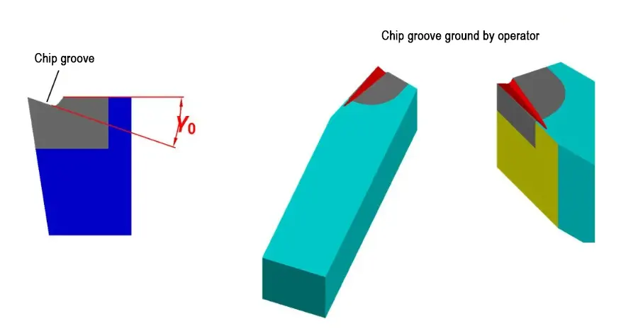
Generally, the front angle γo of a turning tool is selected within the range of -5° to 25°. When turning carbon steel, a high-speed steel turning tool is used with γo selected between 20° and 25°; for a carbide turning tool, during rough turning, γo is chosen between 10° and 15°, and during finish turning, γo is selected between 13° and 18°.
In practice, when machining high-strength materials, to prevent tool damage, a negative front angle is typically used to extend the tool’s service life.
Selection Principles for the Rear Angle αo
The rear angle primarily affects friction during cutting and tool strength.
For rough machining, select a smaller rear angle; for finish machining, select a larger rear angle.
When the workpiece material has high strength and hardness, choose a smaller rear angle to enhance tool strength; when the workpiece is softer, choose a larger rear angle.
If the process system has poor rigidity, reduce the rear angle appropriately to prevent system vibration.
The rear angle αo of a turning tool is generally selected between 4° and 12°. For high-speed steel turning tools, the αo can be chosen between 6° and 8° during rough machining, and between 8° and 12° during finish machining.
Carbide turning tools have poorer toughness than high-speed steel turning tools. Regardless of whether it is rough turning or finish turning, the angle selected should be approximately 1–3° smaller than that of high-speed steel turning tools.
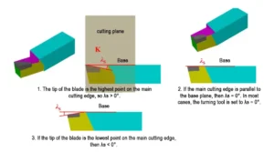
Selection Principles for the Cutting Edge Angle λs
The cutting-edge angle primarily affects the chip inclination, tool strength, and sharpness.
During finishing, λs should be a positive value between 0° and 8°, at which point the tool tip is located at the highest point of the main cutting edge.
During turning, the chips are directed toward the workpiece’s unmachined surface, minimizing contact with the already machined surface, resulting in a lower surface roughness value. However, this approach has the drawback of reduced tool tip strength.
During intermittent turning, due to the impact force, to enhance tool tip strength and protect the tool tip, λs should be set to a negative value of -15° to -5°;
For general turning operations on workpieces with rounded shapes and uniform allowances, λs should be set to 0°.
If the system lacks sufficient rigidity, negative rake angles should not be used, as the increased radial force Fy may cause system vibration and affect machining quality.
Conclusion
Considering the comprehensive effects of tool geometry angles on cutting forces, cutting heat, and tool durability during the cutting process, selecting scientifically reasonable geometric parameters is essential to accurately evaluate the impact of tool geometry angles on the turning process.
FAQ
What are turning tool geometric angles, and why are they important in machining?
Turning tool geometric angles are the specific angular relationships between the tool face, cutting edge, and reference planes. They directly influence cutting forces, heat generation, tool wear, and the overall machining quality, making them crucial for achieving high precision and efficiency.
What are the six basic and two derived geometric angles of a turning tool?
The six basic angles are the central rake angle (Kr), secondary rake angle (Kr′), front angle (γo), main clearance angle (αo), secondary clearance angle (αo′), and edge inclination angle (λs). The two derived angles are the tool tip angle (εr) and the wedge angle (βo).
How does the central rake angle (Kr) affect cutting performance?
The central rake angle influences the distribution of cutting forces, especially the back force (Fp) and feed force (Ff). Increasing Kr can reduce back force, minimizing vibration and deformation, but may raise feed force. Choosing the right Kr helps balance tool strength, heat dissipation, and machining stability.
What is the role of the front angle (γo) in turning operations?
The front angle affects the sharpness of the cutting edge and the amount of metal deformation during cutting. A larger γo reduces cutting force, friction, and heat, improving surface finish and tool life. However, excessive γo can weaken the cutting edge and reduce heat dissipation.
How does the rear angle (αo) influence machining quality?
The rear angle primarily reduces friction between the tool and the workpiece. Larger αo improves surface finish but can reduce tool strength, while smaller αo enhances durability during roughing. Proper selection depends on workpiece hardness, machining type, and system rigidity.
What effect do tool geometric angles have on cutting heat?
Tool geometry directly affects chip formation, friction, and heat dissipation. Larger rake and clearance angles generally lower cutting heat, but excessive values can reduce tool rigidity and lifespan. Optimal geometry balances low temperature with strong cutting edges.
How do turning tool angles impact tool life and durability?
Well-selected geometric angles reduce cutting forces and heat, which slows wear and extends tool life. For example, reducing Kr improves heat dissipation, and optimizing γo lowers deformation. However, incorrect angles can cause chipping, rapid wear, and reduced productivity.
Can proper turning tool angles prevent built-up edge (BUE) formation?
Yes. Increasing γo and adjusting αo appropriately can reduce chip deformation, friction, and heat, which suppresses the formation of built-up edges. This results in smoother surfaces and more stable cutting conditions.
How do tool angles affect machining system rigidity?
Angles like Kr, Kr′, γo, and αo influence how forces are transmitted through the tool, affecting deflection, vibration, and system stiffness. For low-rigidity setups, larger rake angles can reduce cutting resistance and improve stability.
What are the general principles for selecting turning tool geometric angles?
Selection depends on workpiece material, machining type (roughing or finishing), tool material, and system rigidity. Generally, softer materials require larger rake and clearance angles, while harder materials need smaller values to maintain strength. Balancing performance, durability, and heat control is key.
