As manufacturing production models evolve, sheet metal processing has increasingly played a significant role in the manufacturing industry due to its advantages of high efficiency, flexibility, formability, and environmental friendliness.
Additionally, sheet metal processing offers distinct advantages for small-batch, high-variety product processing due to its low initial investment, use of universal tooling, rapid changeover times, and greater suitability for automated production.
Therefore, ensuring that parts are well-suited for sheet metal processing has become an indispensable aspect of production.
As the most widely applied processing method in sheet metal fabrication, the adaptability of product structure to bending processes becomes particularly important.
This article will provide examples and analyses from three aspects: product design, selection of bending dies, and common process optimization methods.
Product Design
Today, engineers’ capabilities must extend beyond their core responsibilities. Product engineers must understand product structure. They must also have a thorough grasp of production processes.
Process engineers must be well-versed in on-site processes. They must also comprehend product design concepts. These two roles complement each other. Both are equally indispensable.
Common Bending Part Design
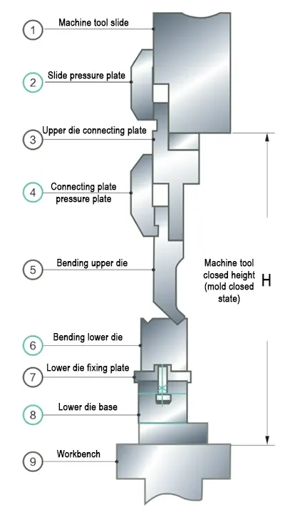
Common bending dies are typically “V”-shaped, with the blank being bent by the combined action of upper and lower dies. The overall working section installation structure diagram is shown in Figure 1.
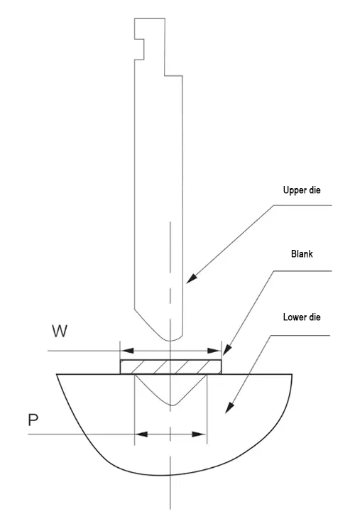
The die structure diagram is shown in Figure 2. As can be seen from the figure, the prerequisite for bending parts is that the blank width W must be greater than P;
Otherwise, the blank cannot be laid flat on the surface of the lower bending die.
This is reflected in the part as the flange height must meet certain conditions.
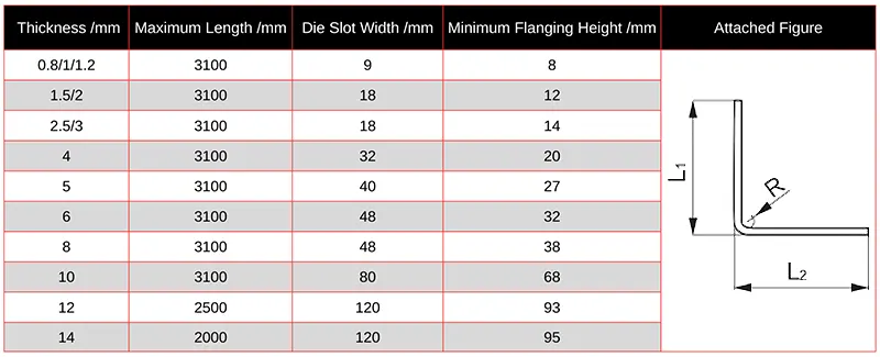
The minimum flange dimensions for different material thicknesses corresponding to the commonly used “L”-shaped bending die are shown in Table 1.
For “Z”-shaped, “U”-shaped, or even more complex shapes, there are more constraints.
Product engineers must consider the convenience and feasibility of the process from the very beginning of product design.
They should base their decisions on the processing capabilities of on-site equipment and dies. This approach helps them avoid designing products that cannot be manufactured.
At the same time, process engineers should summarize and publish the minimum flange heights for different types of bending parts based on actual production capabilities on-site, making it easier for designers to reference.
Only through collaboration and complementarity between product engineers and process engineers can the final parts be better realized.
Product Detail Optimization
(1) Optimization of insufficient local flange height.
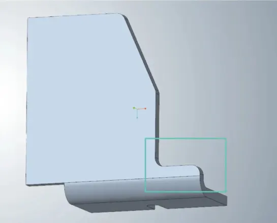
During sheet metal part design, it is inevitable that some local areas will have insufficient flange height. If the flange height is less than the minimum process requirement, direct bending and forming are not possible, as shown in Figure 3.
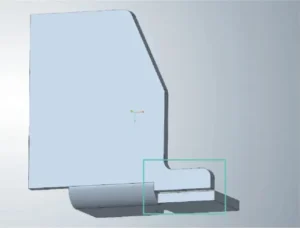
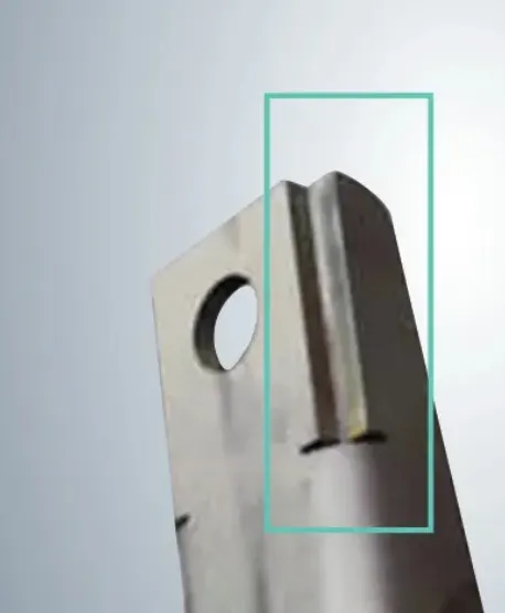
For such cases, consider adding process notches, as shown in Figure 4; or perform a “tear” operation on the area with insufficient flange height and add process notches. The optimized state of this area is shown in Figure 5.
⑵Optimization of hole deformation after bending.
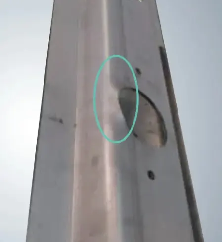
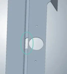
If the hole is too close to the bending line, it will cause deformation of the hole after bending, failing to meet quality requirements, as shown in Figure 6.
For such parts, process notches can be added at the bending line position corresponding to the hole, as shown in Figure 7.
After part optimization, the hole in the part does not deform after bending, fully meeting quality requirements.
The above two cases are common phenomena in sheet metal part design that are often overlooked by product engineers.
If product engineers and process engineers fail to communicate effectively, it can lead to production line stoppages and quality issues, disrupting normal production operations.
However, if product engineers can familiarize themselves with on-site processes in advance, such issues can be avoided.
Bending Die
Bending dies are a crucial component of on-site production, directly determining the site’s processing capacity. The following examples illustrate three common types.
⑴ Standard “V”-shaped bending die.
This type of bending die is the most widely used, primarily for producing “L”-shaped or “Z”-shaped parts. Further examples are not provided here.
⑵ Goose neck Tool.
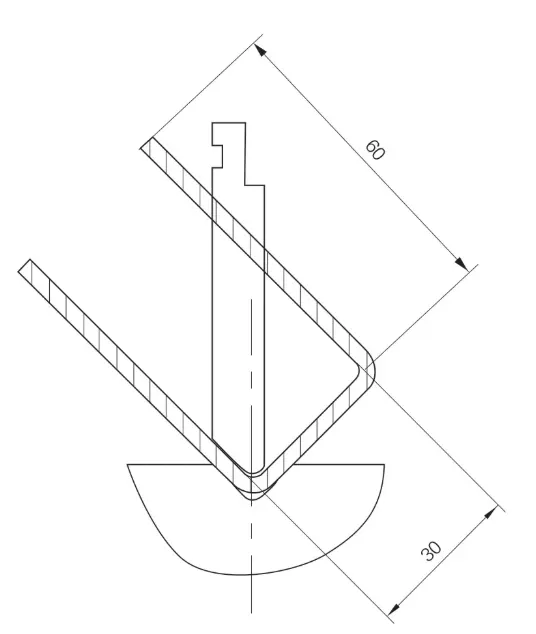
For “U”-shaped parts, during bending, interference between the part and the bending tool prevents the use of conventional bending knives for production, as shown in Figure 8.
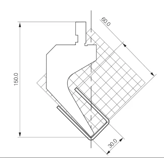
In such cases, a goose neck knife is required. The shape and processing capabilities of the goose neck knife are illustrated in Figure 9.
Taking a goose neck die with a height of 150mm as an example, after one end of the “U”-shaped part is fixed, the grid lines can be used to determine that the maximum flanging height of the other end is 60mm (excluding the material thickness line).
This means that the flanging height of one bending edge of the “U”-shaped part must be less than or equal to 60mm.
Goose neck dies of different sizes have different processing ranges; the larger the height, the stronger the processing capability.
⑶Specialized bending tools.
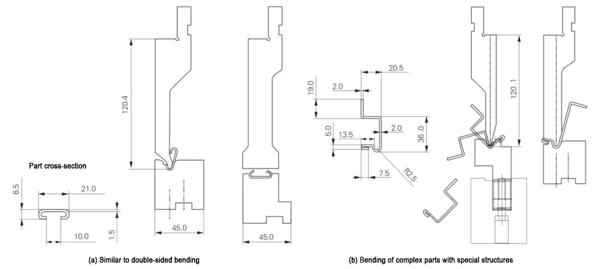
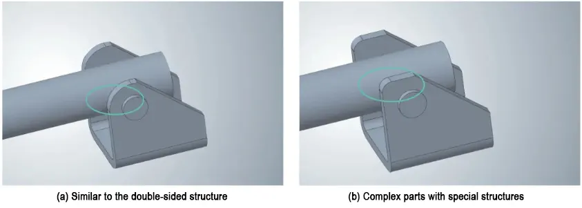
In addition to the above two types of bending, there are parts in actual production that require specialized fixtures to complete the bending process, as shown in Figure 10.
The two types of parts illustrated cannot be produced using conventional bending tools or bending dies, so specialized fixtures must be manufactured.
This relies on the powerful flexible processing capabilities of sheet metal technology for process analysis and optimization.
Ultimately, engineers must integrate product design concepts with on-site processes.
They must ensure that products are manufactured using the most reasonable and suitable methods for actual production. This approach helps them avoid disconnects between theoretical design and practical implementation.
Common process optimization methods
After part design is completed, process optimization can be performed during manufacturing based on actual needs to enhance on-site production efficiency and quality stability.
Adding engraving lines
Currently, sheet metal bending blanks are primarily produced via flat laser cutting. During flat laser cutting, engraving lines can be added at the bending line positions.
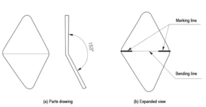
During bending, the process follows the engraving lines, which is particularly evident for irregularly shaped blanks, as shown in Figure 11.
As shown in the unfolded diagram, the blank is diamond-shaped, and the bending line is precisely located at the diagonal of the diamond.
Relying solely on rear positioning during bending can easily result in skewing. Therefore, engraving lines can be added during the flat laser cutting process.
During bending, the engraving lines can be used to assist rear positioning, significantly improving part quality stability and production efficiency.
Optimizing part locating edges
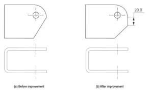
Currently, most bending machines on the market use rear positioning. If the locating edge dimensions of the part are too small, it may cause the part to skew, affecting the final bending quality.
In actual production, the product structure can be locally optimized to increase the length of the straight segment at the end without affecting the part’s functionality, as shown in Figure 12.
Alternatively, the straight segment length can be increased by reducing the R angle, as shown in Figure 13, to make the rear positioning more stable and reliable.
Conclusion
This paper provides a brief overview of the production process of sheet metal bending parts from three aspects: product design, bending die selection, and common process optimization methods.
The content above represents only a small portion of the topics related to sheet metal bending parts.
With the development of new productive forces, new processes and technologies will undoubtedly emerge continuously.
Engineers must continuously enhance their knowledge and skills to better adapt to the evolving industry.
FAQ
Why is sheet metal bending so important in modern manufacturing?
Sheet metal bending is vital because it offers high efficiency, flexibility, and formability while maintaining environmental friendliness. Its ability to adapt to small-batch, high-variety production with low initial investment and quick changeover times makes it an indispensable manufacturing process.
How should product engineers design parts for better sheet metal bending compatibility?
Product engineers should ensure part dimensions, flange heights, and hole placements align with the capabilities of available bending dies and on-site equipment. This prevents design flaws that hinder manufacturability and reduces the risk of production delays.
What are the minimum flange height requirements in sheet metal bending?
Minimum flange heights vary depending on material thickness and bending die type. Designers must reference production capability charts or process engineer guidelines to ensure flange dimensions meet bending feasibility requirements.
How can insufficient flange height issues be resolved during part design?
If flange height falls below the process minimum, engineers can add process notches or tear and notch the affected area. These optimizations allow the part to be bent correctly without compromising structural integrity.
How can engineers prevent hole deformation during sheet metal bending?
When a hole is close to a bend line, deformation may occur. Adding process notches at the bend location near the hole prevents distortion, ensuring the hole maintains its shape and dimensional accuracy.
What are the most common types of sheet metal bending dies?
The most common dies include standard “V”-shaped dies for L- and Z-shaped bends, goose neck dies for U-shaped parts with clearance requirements, and specialized bending tools for complex geometries.
When is a goose neck die used in sheet metal processing?
A goose neck die is essential when bending U-shaped parts where standard dies cause interference. It allows greater flange height clearance, enabling accurate and interference-free bending.
How can engraving lines improve sheet metal bending accuracy?
Adding engraving lines during laser cutting marks precise bending locations. This improves positional accuracy, especially for irregularly shaped blanks, reducing skew and increasing bending consistency.
How can part locating edges be optimized for better bending accuracy?
If the locating edge is too small for stable rear positioning, engineers can increase straight segment length or adjust corner radii. This ensures reliable positioning and higher-quality bending results.
Why is collaboration between product engineers and process engineers crucial in sheet metal processing?
Close collaboration ensures designs match real-world manufacturing capabilities, preventing unfeasible parts, reducing costly redesigns, and improving production efficiency and quality.
