To maximize their functionality, sleeve-type parts are often designed with a focus on lightweight construction and high precision, resulting in relatively low structural rigidity.
Due to the effects of clamping forces, internal material stresses, and cutting stresses, it is difficult to guarantee the required precision of these parts during machining.
By analyzing the structural characteristics of the parts, machining challenges, and factors affecting deformation, we can improve traditional turning tools, machining parameters, and clamping methods to maximize the machining precision of these parts.
Structural Characteristics and Machining Challenges of Parts
The main characteristics of thin-walled sleeve-type parts are a high length-to-diameter ratio and relatively thin walls.
This paper selects a typical thin-walled sleeve-type part with an outer diameter of φ48d8 and an inner bore diameter of φ43H8.
The required surface roughness (Ra) for both the inner bore and outer diameter is 0.4 μm, with coaxiality between different bore diameters of ≤φ0.015 mm and coaxiality between the part’s outer diameters of ≤φ0.015 mm.
The part blank is a φ65 mm round bar, and the manufacturing process consists of: rough machining → heat treatment → semi-finishing → finishing.
After heat treatment, the material’s tensile strength σb is (1380 ± 100) MPa.
Due to the part’s high dimensional accuracy requirements, its 2.5 mm wall thickness, and its 156 mm overall length, machining often causes part deformation and vibration marks on the inner bore walls.
These defects frequently cause the part to fail dimensional and internal surface roughness inspections.
Part Deformation and Influencing Factors
Clamping force, part deformation, internal material stresses, and blank geometry can all affect the machining of thin-walled sleeve-type parts.
These factors can reduce the geometric accuracy of the machined surface below the required level. The resulting deformation typically falls into the following types.
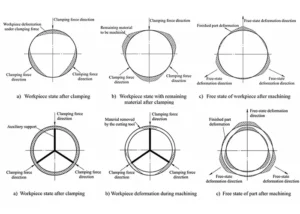
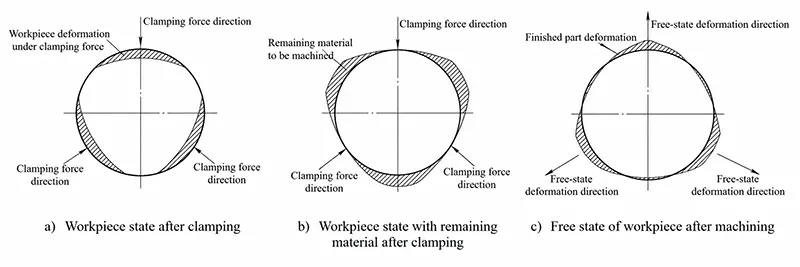
1. When clamping and positioning a workpiece with a CNC lathe fixture, clamping force induces workpiece deformation. Such deformation is usually associated with the clamping scheme and the direction of clamping force.
The amount of part deformation varies with changes in the clamping force, and the two follow a linear relationship.
Figure 1 illustrates the deformation caused by the clamping force when a workpiece is held in a self-centering chuck.
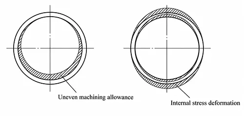
2. When turning the outer diameter and inner bore of sleeve-type parts, if the machining allowance is uneven, it causes uneven release of internal stresses in the material.
As the material seeks a new equilibrium, this can result in roundness and bending deformations of the part.
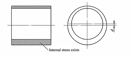
The condition of the sleeve blank in this situation is shown in Figure 2, where the distance d separates the center of the inner bore from the center of the outer diameter.
The deformation of the part caused by internal stresses is shown in Figure 3.
3. Plastic deformation occurs in certain areas of the part.
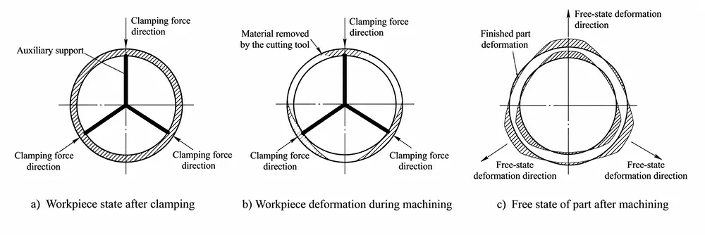
When a part has low rigidity—for example, when machining slender shaft-type parts—insufficient auxiliary support in the fixture can cause plastic deformation after machining in areas with lower precision (see Figure 4).
Identification of Influencing Factors
Due to the poor structural rigidity of thin-walled parts, factors such as clamping force, cutting force, and plastic deformation typically interact and influence one another during machining.
Thus, we can identify deformation sources by measuring workpiece status before and after machining with a lever-type dial indicator.
Plastic deformation is evaluated by measuring workpiece straightness.
Deformation induced by various clamping methods can be distinguished by comparing geometric accuracy between clamped and free states of the workpiece.
We can identify deformation induced by material internal stress release by comparing the workpiece geometry in the free state right after machining and after a resting period.
Due to the interaction between clamping forces and cutting forces, vibrations occur during the machining of thin-walled parts, which not only affect the dimensional and geometric accuracy of the machined surface but also degrade surface quality.
Determining the Machining Process
Based on past machining experience, to minimize part deformation, the part blank undergoes heat treatment after rough machining.
After heat treatment, semi-finish the outer diameter at both ends of the part separately.
Then semi-finish the inner bore with the outer diameter as the datum.
Next, finish-turn the outer diameter with two centers as locating references.
Use the finished outer diameter as the clamping and positioning datum to finish the inner bore.
Lastly, machine features including the sealing groove and annular groove on one end of the part to complete the whole machining process.
Selection of Machining Tools
The materials for these parts are typically precipitation-hardening stainless steels such as 15-5PH or OCr15Ni5Cu2Ti.
Material Characteristics of Precipitation-Hardening Stainless Steel
The chemical composition of 15-5PH is shown in Table 1. Carbon is one of the most important elements in stainless steel;
It exists as an interstitial atom in the iron crystal lattice and is a key factor in enhancing the strength of steel materials.
Chromium forms a substitution-type solid solution in steel, and adding chromium plays a role in increasing strength.
The higher the carbon and chromium content in a part, the higher the strength and hardness it can achieve, thereby meeting the design requirements for sleeve-type parts.
However, as strength and hardness increase, the difficulty of machining these parts also increases exponentially.
Conventional cutting tools lack sufficient hardness to effectively machine high-strength, high-hardness materials.
| C | Mn | Si | P | S | Cr | Ni | Cu | Nb+Ta | Mo |
|---|---|---|---|---|---|---|---|---|---|
| ≤ 0.07 | ≤ 1.00 | ≤ 1.00 | ≤ 0.04 | ≤ 0.03 | 14.0–15.5 | 3.5–5.5 | 2.5–4.5 | 0.15–0.45 | ≤ 0.5 |
Table 1. Chemical Composition of 15-5PH Material (Mass Fraction, %)
Main Deformation Source of Thin-Walled Sleeve-Type Parts
Data sorting and comparative analysis show that the deformation of thin-walled sleeve parts mainly occurs during finish turning of the inner bore.
The initial roughing and semi-finishing operations remove most of the machining allowance.
In the subsequent fine turning of the outer diameter, a double-center clamping method is used;
The clamping forces applied to both the inner bore and outer diameter of the sleeve are minimal, and the process offers high rigidity, preventing vibration and deformation during turning.
By the time the inner bore is precision turned, the sleeve’s bore wall has only a 0.1 mm allowance.
Although soft jaws are used to clamp the outer diameter, the clamping force and cutting force still cause part deformation.
Therefore, it is essential to select an appropriate clamping method and cutting tools.
Tool Selection and Vibration Suppression for Precision Inner Bore Turning
Tool selection is constrained by the ratio of the part’s bore diameter to its depth.
The general principle is to select a tool combination featuring a short shank and inserts with large front and rear angles.
Choosing appropriate tools and a reliable clamping method for finishing can minimize tool deflection and vibration.
When the tool is cutting, the normal cutting force and radial cutting force tend to cause the tool to deviate from the workpiece.
Tangential cutting forces tend to push the tool downward and away from the centerline, thereby reducing the tool’s rake angle.
Any radial displacement results in a reduced cutting depth and thinner chips, which in turn causes vibration.
Combining tool selection criteria and the company’s available tool inventory, we finally chose a specific grade of carbide cutting tool.
The combination of the anti-vibration tool shank and the insert, as shown in Figure 5, can effectively suppress cutting flutter, significantly improve surface quality, and ensure that dimensional and geometric tolerances are consistently met.
This holds even when using extremely slender tool assemblies.

Setting Machining Parameters
The machining process for sleeve-type parts is divided into roughing and finishing, with both roughing and finishing completed in two feed passes.
Based on repeated machining tests, the appropriate machining parameters are set as shown in Table 2.
| Operation | Back Engagement (mm) | Feed Rate (mm/rev) | Spindle Speed (r/min) | Machining Allowance (mm) |
|---|---|---|---|---|
| First Rough Machining | 0.20–0.40 | 0.20 | 800 | 0.30–0.50 |
| Second Rough Machining | 0.05–0.10 | 0.15 | 600 | 0.20–0.30 |
| First Finish Machining | 0.05–0.07 | 0.10 | 400 | 0.10–0.15 |
| Second Finish Machining | 0.03–0.05 | 0.08 | 300 | 0 |
Table 2. Recommended Machining Parameters for Roughing and Finishing
Optimization of Clamping Methods
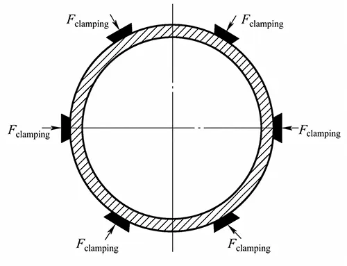
To minimize clamping stress as much as possible, a special six-jaw chuck was designed.
Three two-jaw bases were added beneath a standard self-centering chuck to achieve six-point contact with the workpiece.
This increases the number of contact points between the chuck and the workpiece, significantly reducing the deformation caused by clamping force—even compared to conventional soft jaws.
Figure 6 shows the workpiece clamped in the six-jaw chuck.
Verification of Machining Results
Through verification of multiple batches of machined parts, measurements showed that the roundness of the inner bore of the sleeves—after machining and 48 hours of conditioning at a constant temperature—was consistently maintained within a tolerance of φ0.01 mm.
The results met the machining tolerance requirements for the parts, effectively eliminating the impact of part deformation on the machining process, and the surface quality of the machined parts was correspondingly improved.
A comparison of the surface roughness of the thin-walled sleeves before and after verification is shown in Table 3.
| Category | Average Profile Deviation Ra (μm) | Maximum Profile Height Rz (μm) | Maximum Profile Peak-to-Valley Height Rmax (μm) |
|---|---|---|---|
| Before Validation | 0.713 | 6.570 | 8.110 |
| After Validation | 0.393 | 2.050 | 2.160 |
Table 3. Comparison of Surface Roughness of Thin-Walled Sleeves Before and After Validation
Conclusion
This paper analyzes and investigates the clamping force, internal material stress, and cutting stress that affect deformation during the machining of thin-walled sleeve-type parts.
By establishing a reasonable machining sequence, selecting high-quality insert-and-shank combinations, setting appropriate machining parameters, and optimizing the clamping method, part deformation was minimized, ultimately improving machining accuracy and results.