With the rapid development of the automotive industry, the sector’s demands for engine block CNC machining quality and efficiency continue to rise. As one of the core components of an engine, the engine block features complex free-form surfaces that require high-precision machining using five-axis machining centers.
However, traditional toolpath planning methods struggle to simultaneously meet multiple objectives such as machining accuracy, efficiency, and tool life. This leads to issues like low machining efficiency, severe tool wear, and uneven distribution of residual allowances.
Therefore, there is an urgent need to establish a multi-axis machining path optimization model tailored to the free-form surface features of engine cylinder blocks.
Introducing intelligent optimization algorithms enhances path planning quality and optimizes tool motion trajectories.
This improvement increases machining accuracy and efficiency. It also extends tool life and meets the demands of precision manufacturing for engine cylinder blocks.
Structural Characteristics of Engine Cylinder Blocks
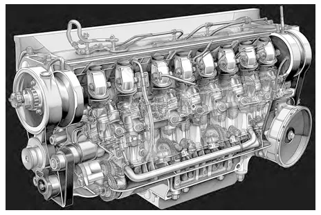
Engine cylinder blocks are integrated structures comprising cylinder blocks and cylinder heads, primarily consisting of multiple cylinder bores, water jackets, oil passages, and other components, as shown in Figure 1.
As the core component of the entire engine, cylinder bores demand extremely high geometric precision. Any minor defect may cause abnormal engine operation.
The inner surface of the cylinder bore exhibits a typical rotary surface structure with a slight taper variation along the axial direction. Surface roughness must be controlled within Ra 0.4 μm.
Complex Free-Form Features of the Cylinder Head
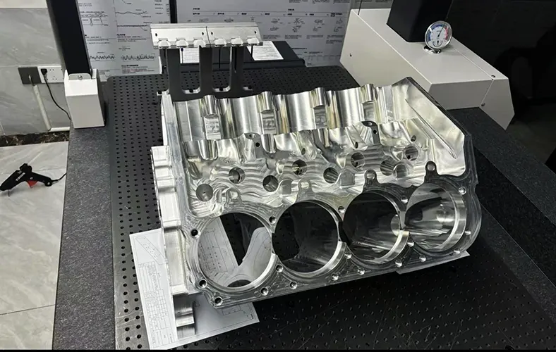
The cylinder head is welded to the cylinder block, forming a complex free-form surface structure.
The cylinder head features multiple guide holes such as intake valve guides and exhaust valve guides, whose inner walls also require precision machining to meet tolerance requirements.
Additionally, the cylinder head incorporates auxiliary structures like grooves and oil holes, which vary in shape and are distributed across dispersed locations.
The curvature radius of the cylinder head surface varies between 50 and 200 mm, featuring multiple corners and uneven areas. This imposes extremely high demands on the smoothness and transition of tool movement trajectories.
Intricate Design of Water Jackets and Oil Passages
The water jacket and oil passages form an integrated structure running through the interior of the cylinder block, exhibiting highly complex shapes.
The water jacket is divided into the cylinder head water jacket and the cylinder block water jacket, interconnected by return pipes.
Oil passages are located inside the water jacket to supply lubricating oil to moving pairs such as pistons and connecting rods. These internal fluid circuits are extremely delicate, demanding stringent machining precision.

Material Selection and Its Impact on Machining
Engine cylinder blocks are typically cast from lightweight, high-strength metals such as aluminum or titanium alloys.
Aluminum alloy blocks offer advantages of light weight and low cost, but their lower strength necessitates the use of fully machined or sprayed wear-resistant liners for cylinder bores.
High-strength metal blocks like titanium alloys provide superior strength and wear resistance but come at a high cost.
Regardless of material, the complex internal structure of cylinder blocks makes the traditional approach of separate roughing and finishing operations inefficient.
Modern Machining Strategies for Precision Manufacturing
In recent years, with the rise of five-axis machining centers, engine cylinder blocks have adopted a rough-semi-finish manufacturing approach.
This method produces a rough blank through a single roughing operation, followed by semi-finishing to achieve the final product.
This not only significantly shortens the process flow but also ensures overall machining accuracy of the cylinder block structure. However, it imposes higher demands on optimizing tool motion trajectories and cutting parameters.
During semi-finishing, multiple cutting strategies must be switched to accommodate the machining demands of different geometric regions.
For instance, during cylinder bore machining, helical interpolation cutting strategies are typically employed to ensure uniform surface roughness.
In the cylinder head surface area, switching to longitudinal segmentation or contour cutting strategies is necessary to guarantee even distribution of cutting allowances.
while in localized intricate structural areas, a zigzag machining mode must be activated to precisely control tool tip height for fine operations like milling and grinding.
Challenges in Multi-Axis Tool Paths During Engine Block Machining
During the machining of complex free-form surfaces in engine cylinder blocks, multi-axis toolpath planning faces numerous practical challenges.
These challenges stem not only from the inherent geometric complexity of the cylinder block structure but are also closely related to dynamic characteristics during machining, machine capabilities, tool conditions, and other factors.
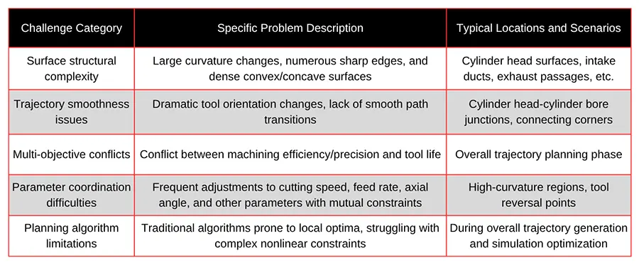
Failure to effectively address these challenges directly impacts machining accuracy, efficiency, and tool life, and may even lead to machining failure, as detailed in Table 1.
Geometric Complexity of Cylinder Block Structures
The engine block comprises multiple structural units, such as cylinder bores, water jackets, oil passages, and cylinder heads.
The cylinder head region, in particular, exhibits highly complex free-form surfaces characterized by numerous geometric features including abrupt curvature changes, localized depressions, and nested passages.
The curvature radii of these surfaces vary significantly (approximately 50~200 mm), while also featuring multiple sharp edges, transition zones, and irregular convex-concave surfaces.
Limitations of Traditional Trajectory Planning Methods
To achieve high-quality machining, the tool must transition smoothly between these structures, ensuring trajectory continuity and surface finish.
However, traditional trajectory planning methods often encounter issues when handling these complex regions, such as abrupt changes in tool movement paths, path irregularities, and localized overcutting or undercutting.
Particularly at points of curvature change and boundary transition zones, the tool is highly susceptible to abrupt acceleration and deceleration movements. This leads to surface defects like vibration marks, scratches, or even overcutting.
Simultaneously, trajectory discontinuities exacerbate load fluctuations in the machine tool’s servo system, compromising the dynamic stability and trajectory tracking accuracy of the machining equipment.
Dynamic and Safety Constraints in Multi-Axis Machining
During multi-axis interpolation, frequent adjustments to the tool axis orientation can lead to issues such as tool tip position deviation, interference, or insufficient retraction paths if the trajectory design is suboptimal.
In severe cases, this may result in tool-workpiece collisions, damaging both equipment and components.
Therefore, achieving trajectory continuity, smoothness, and safety under the complex curved surfaces of cylinder blocks represents one of the core challenges in current trajectory planning.
Multi-Objective Optimization Challenges and Modeling Limitations
During engine cylinder block machining, tool trajectory optimization must balance multiple objectives—including machining quality, efficiency, and tool life—while simultaneously satisfying various physical and engineering constraints.
These include machine movement limits, cutting force stability, thermal deformation control, and tool wear patterns.
Inherent conflicts often exist between these objectives. For instance, increasing cutting speed reduces processing time but may elevate cutting temperatures, thereby compromising machining accuracy and tool life.
Conversely, enhancing path smoothness extends tool usage cycles but potentially sacrifices cutting efficiency.
Tool movement across complex surfaces must also prevent collisions and exceed machine motion limits, necessitating real-time adjustments to parameters like tool axis orientation, feed rate, and cutting depth.
Traditional trajectory planning algorithms, often based on single objectives or empirical rules, struggle to achieve global optimization in multi-objective, multi-constraint environments.
They frequently become trapped in local path optimization, resulting in suboptimal overall machining performance. Issues such as path repetition, excessive length, and path jumps may arise, severely limiting the potential of five-axis machining centers.
Structural Variability and Computational Complexity in Path Planning
Complicating matters further, distinct cylinder block configurations—such as inline, V-type, and horizontally opposed layouts—exhibit significant structural variations.
Parametric models for machining paths lack universality, necessitating repeated modeling and parameter tuning for different components.
This substantially increases computational demands and engineering complexity in trajectory planning.

Multi-Axis Tool Path Optimization for Engine Block Machining
Faced with complex engine block geometries, stringent precision requirements, and multi-objective optimization challenges, there is an urgent need to establish efficient multi-axis tool path optimization methods tailored for free-form surfaces.
Traditional manual path planning approaches are increasingly inadequate for modern engine block manufacturing demands.
Consequently, exploring novel path optimization methods based on advanced technologies like intelligent algorithms and machine learning has become imperative.
This paper proposes an innovative multi-axis toolpath optimization approach integrating machine learning and multi-objective optimization techniques, tailored to the unique geometric and machining characteristics of engine cylinder blocks.
This fundamentally enhances the intelligence and global optimization capabilities of toolpath planning, promising significant improvements in machining accuracy and efficiency, extended tool life, and robust technical support for high-quality cylinder block processing.
Machine Learning-Based Intelligent Tool Path Generation Method
During engine cylinder block machining, employing a machine learning-based intelligent tool path generation method is a crucial technical approach to enhance processing efficiency and quality.
This method utilizes machine learning algorithms to automatically optimize and generate tool paths, addressing the complex free-form surfaces and precision machining demands of engine cylinder blocks.
> Feature Extraction for Intelligent Path Generation
In machine learning-based tool path generation, key features influencing path generation are extracted from historical machining data.
These features include, but are not limited to, workpiece geometric parameters, material properties, target surface roughness, tool type, and dimensions.
Feature extraction converts complex machining requirements into algorithm-processable input vectors.
A feature vector X = [x₁, x₂, …, xn] can be constructed, where xi represents the various features mentioned above.
> Preparation and Importance of Training Data
Next, training data must be prepared, typically comprising tool paths under multiple machining scenarios and corresponding evaluation metrics such as machining time, completion rate, and surface quality.
This data can be obtained from actual machining processes or generated using advanced simulation software.
The quality of training data directly impacts the model’s learning effectiveness and prediction accuracy.
> Model Selection and Deep Learning Implementation
Using the extracted features and prepared training data, an appropriate machine learning model can be selected for training.
In tool path optimization applications, commonly used models include Random Forests, Support Vector Machines, or deep learning networks such as Convolutional Neural Networks (CNNs) and Recurrent Neural Networks (RNNs).
Researchers employ deep learning models to predict the optimal position and direction of tool movement at each step. The model’s output represents the next optimal tool position yt, determined by current and past states, as shown in Equation (1):

where Xt is the current input feature vector, comprising the workpiece’s current machining state and tool position; θ denotes model parameters; and f represents the deep learning model.
> Continuous Optimization and Application in Engine Block Machining
After training, the model can automatically generate optimized tool trajectories based on input workpiece features and machining conditions.
This intelligent path generation not only reduces human intervention and enhances path planning efficiency but also continuously optimizes the trajectory generation algorithm through ongoing learning and adaptation to new machining conditions.
Through the above steps, the machine learning-based intelligent toolpath generation method effectively addresses the complexity and diversity in engine block machining, enhancing machining accuracy and efficiency.
Implementing this approach is expected to significantly improve engine block machining quality, meeting the demands of modern automotive industry for high-performance engines.
Multi-Objective Modeling-Based Path Optimization and Solution Strategy
In engine block machining, multi-axis tool path optimization presents a complex challenge involving multiple objectives such as precision, efficiency, and tool life.
To achieve an optimal balance among these goals, a multi-objective modeling-based path optimization and solution strategy can be employed.
> Construction of the Multi-Objective Optimization Model
For multi-axis tool path optimization in engine block machining, a multi-objective optimization model encompassing all key performance indicators must be constructed.
This model typically aims to minimize machining time, maximize machining accuracy, and maximize tool life. These objectives inherently conflict—for instance, reducing machining time may compromise accuracy and accelerate tool wear.
Mathematically, this can be formulated as the optimization problem shown in Equation (2):

where f₁(x) represents machining time; f₂(x) represents surface roughness (a proxy for machining accuracy); and f₃(x) represents the expected tool life.
Each objective function correlates with tool trajectory parameters x (including cutting speed, feed rate, depth of cut, etc.).
This model must also incorporate constraints such as machine tool physical limitations, safety protocols, and material cutting characteristics.
Due to the complexity of multi-objective optimization problems—particularly when involving uncertainty and nonlinearity—traditional optimization methods may struggle to find global optima.
> Application of Intelligent Heuristic Algorithms
Therefore, employing modern heuristic algorithms—such as genetic algorithms (GA), particle swarm optimization (PSO), or multi-objective evolutionary algorithms (MOEA)—has become an effective approach for solving such problems.
These algorithms can efficiently search for trade-off solutions across multiple objectives within large search spaces while adapting to complex constraints.
A critical step in algorithm implementation is defining an appropriate fitness function to evaluate solution quality.
In multi-objective optimization, the Pareto frontier is commonly used as a performance metric. This frontier represents the optimal trade-off set of all objectives where no single objective can be improved without sacrificing others.
> Achieving Global Optimization and Improved Machining Performance
The fitness function can be defined as shown in Equation (3):

where w₁, w₂, w₃ are the weighting coefficients for each objective, which can be adjusted according to specific production requirements.
Ultimately, this multi-objective optimization-based toolpath generation method provides a systematic solution for handling complex machining requirements.
It enhances production efficiency and tool usage economics. At the same time, it ensures machining quality through the application of intelligent algorithms.
Implementation of this method is expected to significantly optimize the machining process of engine cylinder blocks, improving overall production performance and reliability.
Conclusion
In summary, this paper addresses the multi-axis toolpath planning challenges encountered during the machining of complex free-form surface engine cylinder blocks.
It proposes an intelligent trajectory generation method based on machine learning and a trajectory optimization strategy based on multi-objective modeling.
The former automatically extracts machining patterns from historical optimized trajectories and employs deep learning technology to intelligently generate initial trajectory schemes, reducing manual intervention.
The latter constructs an optimization model that comprehensively considers multiple objectives such as machining efficiency, precision, and tool life.
It designs a hybrid intelligent optimization algorithm solution that effectively balances the conflicts among these objectives to obtain the overall optimal cutting path.
This method overcomes numerous challenges faced by traditional path planning approaches, providing a new technical pathway for achieving high-precision machining of complex free-form surfaces in engine cylinder blocks.
It also offers valuable insights and guidance for the intelligent manufacturing of other types of curved parts, demonstrating significant theoretical value and promising engineering applications.
FAQ
What makes multi-axis toolpath optimization essential for engine block machining?
Multi-axis toolpath optimization is essential because engine blocks feature highly complex free-form surfaces that require precise and smooth tool motion. Optimizing the toolpath improves machining accuracy, reduces tool wear, and increases efficiency—key factors for meeting the automotive industry's growing precision demands.
Why do traditional toolpath planning methods fall short in engine block machining?
Traditional toolpath planning often focuses on single objectives, such as speed or accuracy. This limitation prevents them from balancing multiple goals like machining precision, efficiency, and tool life. As a result, traditional methods can cause irregular tool motion, uneven material removal, and faster tool degradation.
How does machine learning improve CNC toolpath generation for engine blocks?
Machine learning algorithms analyze historical machining data—such as surface geometry, tool type, and cutting parameters—to automatically generate optimized toolpaths. This intelligent approach reduces manual programming, enhances trajectory smoothness, and adapts dynamically to complex surface variations during machining.
What are the main challenges in multi-axis machining of engine cylinder blocks?
The main challenges include managing complex geometries, avoiding tool collisions, maintaining trajectory continuity, and balancing multiple objectives like accuracy, efficiency, and tool life. Additionally, the machine’s dynamic limits, tool orientation changes, and surface curvature transitions further complicate toolpath planning.
How do intelligent algorithms enhance machining efficiency and accuracy?
Intelligent algorithms—such as genetic algorithms and particle swarm optimization—analyze multiple machining parameters simultaneously. They identify optimal combinations that minimize machining time, maximize precision, and extend tool life, leading to higher productivity and lower operational costs.
What role does multi-objective optimization play in engine block CNC machining?
Multi-objective optimization allows engineers to balance conflicting goals like speed, surface quality, and tool longevity. By using advanced mathematical models and Pareto front analysis, it ensures that no single objective is optimized at the expense of others, resulting in the best overall machining performance.
Why are engine cylinder blocks difficult to machine with conventional methods?
Engine cylinder blocks have intricate internal structures—such as cylinder bores, oil passages, and water jackets—with varying curvature radii and tight tolerances. Conventional machining methods struggle to maintain uniform surface finish and dimensional accuracy across these complex surfaces.
What materials are commonly used for engine cylinder blocks, and how do they affect machining?
Engine blocks are often made from aluminum alloys for lightweight applications or titanium alloys for high strength. Aluminum is easier to machine but requires surface reinforcement, while titanium demands more precise toolpath control due to its toughness and low thermal conductivity.
How does the proposed machine learning-based toolpath model work?
The model extracts geometric and machining features, trains a neural network using past machining data, and predicts the next optimal tool position in real-time. This continuous learning process generates adaptive, collision-free trajectories that enhance both efficiency and surface quality.
What are the benefits of implementing multi-axis toolpath optimization in modern manufacturing?
Implementing optimized toolpaths enhances machining accuracy, reduces cycle time, extends tool life, and minimizes manual intervention. It also ensures consistent quality across complex parts like engine blocks—meeting the precision and efficiency standards of Industry 4.0 smart manufacturing.

