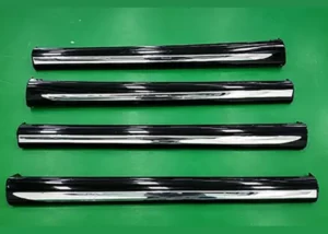
Chrome trim is widely used in passenger cars, both on the exterior and interior. On the exterior, it is primarily used on the grille, bumpers, emblems, and body side moldings. On the interior, it is used on air vent bezels, instrument panel bezels, handles, and buttons.
The use of chrome trim elements effectively enhances the vehicle’s high-tech and luxurious feel, elevating its overall quality.
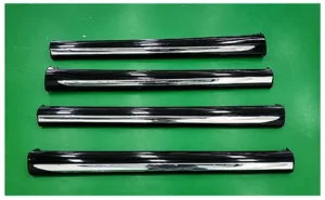
In 2021, a certain model produced by Fujian Mercedes-Benz Automotive Industry Co., Ltd. required the addition of four new electroplated trim components.
These components were made of electroplating-grade PC+ABS, with the final product featuring a chrome-plated surface.
Each component was over 1 meter long and featured thin walls; its spatial geometry had to conform to the curves of the vehicle body rather than a simple flat structure.
As a result, they were highly prone to warping and deformation after electroplating, making development extremely challenging.
Development Process and Production Results
My team developed this product in accordance with the APQP process and carried out iterative refinements. Meanwhile, we worked together with suppliers to tackle a series of problems across the full workflow.
These stages cover product conceptualization, raw material screening, mold development, and mass production.
Finally, the product achieved stable on-vehicle assembly and large-scale export. No customer complaints have been received for this product after years of volume production.
This outcome validates the rational design and dependable quality, bringing substantial economic and social benefits.
This paper summarizes the difficulties encountered in design, development, trial manufacturing, and early mass production, and extracts corresponding experience.
It is hoped that this will provide practical guidance for the design, development, and manufacturing of similar products, helping to avoid or minimize detours in the process.
Product Requirements and Constraints
This electroplated trim is a cosmetic part, and its outer surface is classified as a Grade A surface.
Grade A surfaces have the highest surface quality requirements; furthermore, the electroplating process magnifies microscopic surface defects, which may become very noticeable after plating.
The requirement for a plating process on an exterior trim component increases the difficulty of designing and manufacturing this part.
Since no structural features can be incorporated into the matching side skirt, this product must be installed using adhesive tape.
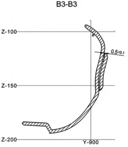
Figure 1 shows the assembly of the plated trim and the side skirt. Once installed, the trim must fit snugly against the skirt; the gap requirements are shown in Figure 2.
If the adhesive tape detaches from either the trim or the skirt—even if only in a localized area—the detachment will spread over time due to prolonged exposure to wind, sun, rain, and dirt.
In severe cases, the trim may fall off, leading to batch-wide quality issues and customer complaints.
Feasibility Analysis of the Original Design and Improvement Plan
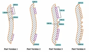
Figure 3, Part Version 1, shows a cross-sectional view of the part’s original design.
The analysis identified flaws in this design. The transition between the top and bottom surfaces at the parting line formed a sharp corner.
This geometry easily led to inadequate material filling and over-cooling. These problems led to stress concentration and difficulty in molding.
During the electroplating process, electric field lines converge at sharp corners, causing material to accumulate there and resulting in scorching and excessively thick plating.
Defect Analysis and Structural Optimization of the Part Profile
After optimizing the design, Part Version 2 was developed.
The sharp corners were removed, and a 0.2–0.5 mm transition section parallel to the mold opening direction was added, along with a draft angle.
This transition section enhances the local strength of the part and helps prevent defects such as mold-induced scratches.
At the same time, our team produced prototype parts via 3D printing and conducted test assemblies. We found that the part’s end sections did not fit well with the mating component.
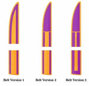
Adopting the original tape layout (Figure 4, Tape Version 1) would likely cause weak adhesion at the trim terminal and trigger mass production quality risks.
Tape cutting relies on manual operation. Operators struggle to cut the tape precisely to the length and shape defined in drawings. If the tape is too short, it fails to fully cover the trim end.
A gap forms between the part and its mating counterpart after assembly, and the trim edge curls upward. If the tape is overlong or misaligned during manual attachment, squeezing after assembly exposes the tape and creates cosmetic defects.
Improvement of Adhesive Tape Scheme for Assembly Terminals
To solve this problem, a custom die-cut tape (Figure 4, Tape Version 2) was developed.
It removes the requirement for manual cutting. Moreover, this redesigned die-cut tape has a larger contact area and higher bonding force, securing stable adhesion at the part terminal.
Issues and Improvement Measures
Parts Sticking to the Upper Mold After Injection Molding
During the initial trial run of prototype parts using the mold, the author observed that after the mold opened, the parts remained stuck to the upper mold.
The parts had to be removed manually, and upon removal, they were severely deformed and unusable. The analysis attributed this phenomenon to vacuum suction.
It arises from the mirror-polished surface of the upper mold, together with the absence of structural features on the moving mold half.
When the mold opened, the component stuck to the upper mold. The suction force from the upper mold overcame the frictional force on the moving mold side.
To solve this defect, the author investigated candidate countermeasures. Options included texturing the lower mold surface and adding ribs on the B-side of the part.
The pros and cons of each scheme were assessed. Ultimately, the solution adopted was to add a 1-mm rib to the part’s B-side.
This not only resolved the suction issue but also helped prevent part deformation (Figure 3, Part Version 3). The dimensions of these ribs were verified using mold flow analysis software and optimized through iterative adjustments.
The goal was to resolve the part sticking to the upper mold issue while avoiding defects such as noticeable sink marks on Side A that could compromise the part’s surface quality.
By implementing this solution, the part sticking to the upper mold issue was resolved. The added ribs did not cause any noticeable sink marks on Side A of the product and did not affect the part’s surface quality.
Improvements to Issues Identified During Trial Assembly
The author used Part Version 3 shown in Figure 3 for testing. Fixtures guaranteed the required clamping force and dwell time while applying adhesive tape. Prototype samples were then subjected to environmental chamber tests for performance evaluation.
At the opposite end and local middle regions, the clearance between the trim strip and matching component exceeded the design specification of 0.5 mm ± 0.1 mm (Figure 2).
An extra segment of adhesive tape was added to this end as a countermeasure. The tape width was enlarged from 5 mm to 8 mm (Figure 4, Tape Version 3).
Repeated prototype verification showed that the gap between the trim strip and mating part satisfied design requirements over the full length.
Environmental testing was repeated after the trim strip was assembled. The tests covered conditions such as low temperature, temperature cycling, and high temperature and humidity.
After testing, the trim strip showed no detachment, and the adhesive tape pull-off force exceeded 150 N, meeting all design requirements.
Highlights and Improvement Measures for Parting Lines During the Initial Mass Production Phase
In the early mass production stage of this component, our team found that scattered yet fixed bright spots emerged along the parting line after electroplating once roughly 5,000 pieces had been manufactured.
These spots had a granular texture when touched. Analysis confirmed the root cause: insufficient hardness of the upper mold material.
As production continued, slight abrasion and material loss occurred near the parting line. The upper mold is made of XPM ESR, a pre-hardened mold steel that does not require heat treatment during use.
This steel offers excellent polishability, capable of achieving a mirror finish, and is widely used in large molds for automotive headlights, bumpers, instrument panels, and similar components.
However, this steel has a relatively low hardness of only about 35° HRC. During production, wear and material loss on the upper die were caused by impacts between the upper and lower dies during closing, compression of residual metal shavings, and scratches during opening.
While the die’s functionality could be restored through methods such as grinding the cutting edges, grinding does not fundamentally resolve the issue;
The problem would recur, and repeated grinding would damage the die’s cutting edges.
Root Cause Analysis of Bright Spot Defects on the Parting Line
Ultimately, the author decided to replace the mold material and remanufacture the upper mold cavity.
The new material selected was 1.2343ESR, a hot-work die steel commonly used in die-casting molds but also suitable for plastic molds that require high polishability and wear resistance.
After heat treatment, this material can achieve a hardness of 48–52° HRC.
Furthermore, to improve the strength of the component around the parting line and mitigate scratching during mold release, we lengthened the transition zone and raised the wall thickness near the parting line.
This modification was realized by adjusting the outer surface contour (Figure 3, Part Version 4).
Mold Material Replacement and Structural Reinforcement Measures
Following this round of improvements, the highlight issue was resolved, and the trim part reached its final design.
Since 2022, it has been installed in vehicles in volume and exported.
Product quality is stable, the scrap rate during production is very low, and there have been no related customer complaints since installation.
Recommendations for Design Optimization of Similar Parts
Part Structure
The electroplated trim strip developed by our team was added after the vehicle model entered mass production.
Since the mating part could not be modified, this imposed numerous limitations—such as the inability to conceal the trim strip’s parting line and the necessity to use adhesive tape during assembly.
If the trim strip and its mating part had been considered comprehensively during the early stages of vehicle development, targeted design adjustments could have been made to avoid such issues.
1. Limitations of Post-Release Retrofit Design
Possible measures include:
(1) Use a combination of locating pins, snap-fits, and adhesive tape for assembly between the trim strip and mating parts.
Relying solely on adhesive tape places high demands on the tape’s performance, the cleanliness of the bonding surface, the pressure applied during application, and the holding time.
Using locating pins to assist with assembly can improve positioning accuracy.
Snap-fits can improve assembly reliability and effectively prevent trim strips from curling up or falling off, especially at the ends of the trim strips.
(2) Achieve a hidden parting line after assembly through structural design.
Such plated parts are prone to cosmetic defects, such as bright spots, along the parting line, which are difficult to avoid during mass production but have no impact on the product’s actual functionality.
By incorporating structural features into the mating part—such as a recessed groove—the parting line can be concealed after the trim strip is assembled, making minor defects along the parting line invisible.
This design lowers the requirements for product appearance quality and can reduce scrap rates and costs associated with mold modifications.
(3) Prevent vacuum adhesion through part and mold structural design.
The exposed surfaces of electroplated parts typically require a mirror-finish level of smoothness, which can cause the part to adhere to the upper mold during mold opening due to vacuum suction.
Furthermore, because of the high standards for the exposed surfaces, it is not possible to install venting mechanisms on the upper mold (as this would leave marks or flash on the part’s surface).
Therefore, structural features such as ribs should be incorporated into the part’s inner surfaces, or the lower mold cavity should be roughened to increase friction, thereby forcing the part to remain in the lower mold during opening.
2. Recommended Design Strategies for Early Development Stage
The use of die-cut tape can simplify the process and improve quality. Die-cut tape eliminates defects like incorrect length and distorted outlines from manual cutting.
It also prevents contamination and degraded bonding strength. These problems occur when operators touch the adhesive side during cutting.
Mold Material Selection
XPM ESR or alternatives with similar performance, such as the 718/1.2738 series, are lower in price and hardness.
During continuous production, factors such as collisions during mold closing, excessive clamping force, excessive injection pressure, or foreign objects trapped in the mold may cause fine surface pitting or material loss on the mold surface.
While these defects are not noticeable on the plastic part itself, they become visible after electroplating. This factor must be considered when selecting mold materials.
If necessary, upgrade to a material with higher hardness, such as 1.2343ESR or a similar product. Although such materials cost nearly twice as much as XPM ESR, they offer superior performance.
In summary, the selection of mold materials should not focus solely on price or the blind pursuit of reducing mold costs.
Factors such as operating conditions, cost, and mold service life must be considered comprehensively.
Conclusion
This article summarizes the experience gained from the successful development of a class of long, thin-walled electroplated trim parts and serves as a highly valuable reference.
Such parts have stringent aesthetic requirements and are prone to deformation.
Therefore, it is essential to optimize the design as much as possible—using methods such as concurrent engineering—from the early conceptual stage to proactively address and prevent potential issues that may arise during later production stages.
This approach reduces the time required for mold modifications and debugging, thereby ensuring stable production and enhancing product quality.