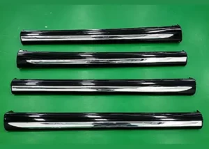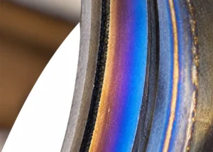
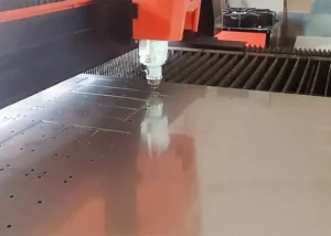
As advanced manufacturing technologies evolve toward lightweight and high-precision applications, the proportion of thin-gauge metal components used in industries such as aerospace, automotive manufacturing, and electronics continues to rise.
The quality of their edge processing has become one of the key indicators determining the assembly accuracy and in-service performance of these components.
Thanks to its technical advantages—including non-contact processing, a narrow heat-affected zone, and high processing flexibility—laser cutting has gradually become the mainstream process for precision cutting of thin metal sheets;
However, the burrs inevitably produced during this process not only reduce the surface precision of the workpiece but also require additional processing steps to meet usage requirements.
Conventional deburring techniques include mechanical grinding and chemical etching. They commonly have obvious drawbacks: low throughput, high risk of surface damage, and heavy environmental pollution.
Such methods struggle to match the requirements of modern high-efficiency and green manufacturing. Under this background, it is meaningful to systematically reveal how laser-cut burrs form.
We also need to clarify the coupling relationship between process parameters and burr features. Developing high-efficiency integrated laser deburring technology carries great theoretical and practical value.
It helps raise the manufacturing quality of thin metal parts and broaden the engineering adoption of laser processing.
Laser Cutting Technology for Thin Metal Sheets
Principles and Characteristics of Laser Cutting
Laser cutting involves directing a high-energy-density laser beam onto the surface of a material, causing a localized area to instantly reach temperatures high enough to melt or even vaporize the material.
An auxiliary gas, flowing coaxially with the beam, then blows the molten material out of the cut, thereby separating the material.
Depending on the mechanism of interaction between the laser and the material, cutting methods can be classified into fusion cutting, vaporization cutting, oxidation cutting, and controlled fracture cutting.
Among these, fusion cutting dominates the processing of thin metal sheets due to its high energy utilization efficiency. The highly focused nature of the laser beam allows its energy density to reach the order of 10⁶ to 10⁸ W/cm².
This extremely high power density quickly melts the target material. Accurate control of the laser beam path also enables precise cutting of intricate profiles.
This technology provides strong technical support for lightweight designs in aerospace, electronics manufacturing, and other related industries.
A Study on Process Parameters for Laser Cutting of Thin Metal Sheets
Laser power, cutting speed, defocus amount, and assist gas pressure constitute the core set of process parameters that affect the quality of thin-sheet cutting.
Laser power determines the total amount of energy absorbed by the material;
If the power is too low, insufficient melting will prevent the material from being cut through, while if it is too high, excessive ablation may occur, leading to slag buildup on the edges of the cut.
Cutting speed affects the duration of interaction between the laser and the material; Excessive speed prevents molten material from being evacuated in time, resulting in burrs.
Defocus directly alters the spot size and energy density distribution. Negative defocus places the focal point inside the material. It yields a more consistent kerf width.
Positive defocus sets the focal point above the material surface. This condition easily triggers excessive ablation on the top surface and incomplete cutting through the bottom.
For instance, Zhai Zhaoyang carried out cutting tests on 0.2 mm-thick 304 stainless steel foils.
With the parameter set: laser power 125 W, cutting speed 10 m/min, shielding gas pressure 1.2 MPa, and defocus of −0.3 mm, the burr thickness was limited below 10 μm, and the slag spatter zone width stayed under 50 μm.
The Formation and Suppression of Burrs in Laser Cutting
Analysis of the Mechanism of Burr Formation and Influencing Factors
The formation of burrs during laser cutting stems from the non-equilibrium evolution of molten metal during the solidification phase.
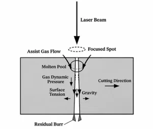
As shown in Figure 1, when the laser scans across the material surface, the temperature in the irradiated area rises sharply, causing a phase transition in the metal and forming a liquid molten pool;
The assist gas applies shear force to the molten material within the pool in the form of a high-speed gas flow to expel the molten material from the cut.
However, the molten metal at the bottom of the cut is subject to the coupled effects of surface tension, gravity, and gas flow pressure;
As a result, some of the molten material cannot be completely expelled and remains at the edges of the cut, forming burrs.
Although increasing the laser power can enhance the degree of material melting, excessively high energy density causes the molten pool to expand in volume, significantly increasing surface tension;
If the gas flow’s slag removal capacity cannot keep pace with the rate of molten material generation, large spherical slag droplets will adhere to the lower surface of the cut.
When the cutting speed is too low, excessive heat accumulates per unit length of the cut, which can easily lead to over-ablation;
Conversely, if the cutting speed is too high, the molten material may solidify before it has had time to flow sufficiently.
Furthermore, the degree of defocusing can affect the uniformity of ablation in the cut zone by altering the gradient of energy density distribution across the thickness of the material.
Burr Control Based on Process Parameter Optimization
Burr thickness is a key indicator for evaluating cutting quality. Its value exhibits a quantifiable functional relationship with laser power, cutting speed, and defocus amount.
Establishing a mathematical model linking process parameters to burr characteristics can provide theoretical guidance for parameter optimization.
Based on heat conduction theory and fluid dynamics principles, the thickness h of the molten layer at the bottom of the cut can be approximately expressed as:
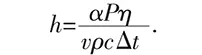
In the equation:
- α is the material’s laser absorption coefficient, dimensionless;
- P is the laser power, in W; η is the beam utilization efficiency coefficient, dimensionless;
- v is the cutting speed, in m/min; ρ is the material density, in kg/m³; c is the specific heat capacity, in J/(kg·°C);
- Δt is the temperature difference between room temperature and the melting point of the material, in °C.
This formula describes how laser power P and cutting speed v oppositely regulate molten layer thickness. Raising laser power increases the thickness of the molten layer.
Increasing cutting speed cuts down energy input per unit cutting length. As a result, the molten layer becomes thinner.
A reduction in the thickness of the molten layer means a corresponding decrease in the volume of residual molten material, which in turn suppresses the formation of burrs.
For example, optimization of the cutting process for 304 stainless steel thin sheets shows that, with a power of 125 W and a speed of 10 m/min, combined with a negative defocus setting of -0.3 to -0.5 mm and a nitrogen pressure of 1.2 MPa, the burr thickness can be reduced to less than 10 μm.
Laser Deburring Technology and Applications
Working Principles and Structural Design of Laser Deburring
The core principle of laser deburring technology is the selective energy deposition on the burr area using a laser beam: by precisely controlling the laser power density, the burr is heated to its melting temperature while ensuring the temperature of the base material remains below a safe threshold, thereby achieving precise, localized removal of the burr.
Traditional laser deburring systems employ a single focused spot scanning process.
This approach removes large burrs effectively but shows limited performance against micro-burrs and irregular edge protrusions formed during cutting. Multiple repeated laser scans are generally required to meet surface smoothness requirements.
To address this drawback, researchers at the Fraunhofer Institute for Laser Technology in Germany developed a beam-splitting optical system for laser deburring.
Incident laser light is divided into two beams of different energy densities within this system. The high-intensity central beam eliminates bulky burrs, while the surrounding annular beam at lower energy density melts and smooths fine residual edge defects.
Optical components including a focusing lens, a cylindrical mirror, and a parabolic mirror form this beam-splitting configuration along the light path.
The central laser fraction travels straight through the focusing lens to generate the inner high-energy beam. Peripheral light strikes the cylindrical mirror at a 45° incidence angle and reflects toward the parabolic mirror.
A subsequent reflection off the parabolic mirror yields the coaxial outer annular beam. With this dual-beam cooperative strategy, burr removal and edge rounding can be accomplished in a single scanning pass.
Optimization of Deburring Process Parameters
The core of laser deburring parameter optimization lies in balancing removal efficiency and substrate protection. Proper matching of laser energy input and scanning motion ensures complete melting and removal of burrs.
At the same time, it prevents excessive thermal damage and edge distortion of the workpiece. This balance requires systematic process trials tailored to specific materials and burr shapes. The goal is to identify a stable optimal parameter window.
Parameter configurations should adapt to burr dimensions, material grades, and target surface quality. Laser power, scanning speed, and defocus amount together construct the three-dimensional optimization space.
This parameter set works well for medium-sized burrs ranging from 20 μm to 50 μm thick: laser power of 800–1200 W paired with a scanning speed of 8–10 m/min.
Excessively high power easily overmelts the substrate edge and creates new protrusions. Insufficient power fails to fully melt through the burr and leaves residual material behind.
A higher scanning speed narrows the heat-affected zone. Raising the speed from 6 m/min to 12 m/min shrinks the heat-affected width from 150 μm down to below 80 μm.
Yet an overly fast scan shortens the laser-burr interaction time. The melting depth becomes inadequate; some burrs are only cut apart instead of being fully stripped away.
Defocus controls spot size and energy density distribution directly. A negative defocus of −0.5 mm to −1.0 mm concentrates laser energy near the burr root.
This makes it easier to separate the burr from its base. Under positive defocus, energy spreads out at the burr tip, which prevents complete removal.
Engineering Applications and Results of Laser Deburring
Laser deburring technology has been pioneered for large-scale application in the automotive manufacturing sector. High-precision castings, such as engine blocks and transmission housings, are suitable for laser deburring.
Laser light delivered through optical fibers can access deep, enclosed cavities. It avoids dust contamination and tool wear common in manual grinding.
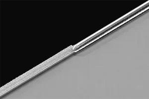
Figure 2 shows typical burr features on laser-cut thin metal sheets. Protruding burrs along cutting edges stand 30–50 μm high. These edges have poor surface roughness and irregular fusion traces.
These edge defects undermine assembly accuracy. They also form stress concentration sites during operation, and may trigger fatigue cracks.
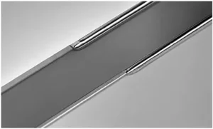
After laser deburring, the quality of the workpiece edges was significantly improved (see Figure 3). The original sharp burrs were completely removed, and the cut edges exhibited a smooth, rounded transition.
The surface roughness (Ra) value was reduced to below 3 μm, with continuous and uniform edge profiles and no noticeable discoloration in the heat-affected zone.
Laser deburring is applied for edge finishing of aero-engine blades. It accurately removes micro-burrs generated during casting or machining and induces no mechanical stress.
Unlike chemical deburring, this technique does not require immersion in corrosive liquids. It shortens the production cycle and lowers environmental contamination risks.
This method also fits precision stamped components in electronics manufacturing. Thin-walled workpieces (0.1–0.3 mm thick) often develop flanging and tearing burrs after punching. Laser deburring realizes edge rounding via localized melting.
From a cost-effectiveness perspective, laser deburring systems can process parts 3 to 5 times faster than traditional methods;
Furthermore, this technology requires no consumables and produces no waste, reducing the per-unit processing cost by approximately 40% under mass production conditions.
Conclusion
The key to quality control in laser cutting of thin metal sheets lies in effectively suppressing burr defects.
By analyzing the physical mechanisms underlying burr formation and clarifying the coupling relationship between melt pool dynamics and process parameters, we can provide a theoretical foundation for parameter optimization.
Through the appropriate matching of process parameters, burr thickness can be reduced to the micrometer scale, significantly improving the quality of the cut surface.
Laser deburring relies on an innovative beam-splitting optical layout. It integrates burr removal and edge rounding efficiently within a single process.
This technology offers attractive industrial advantages: low cost, high throughput and strong process adaptability. Two core directions deserve priority in follow-up studies.
One targets intelligent adaptive control systems for tuning process parameters. The other focuses on miniaturized, modular hardware for laser deburring. Progress in these areas will promote wider adoption of the technique across manufacturing sectors.