In the field of heavy equipment, large shaft components often require ultra-deep hole machining to reduce weight, improve material utilization, and meet special structural requirements.
Currently, some scholars have conducted in-depth research on the service life of spindles, hollow shafts, and deep hole machining processes.
They conducted a comparative analysis of hollow shafts and solid shafts.
They found that hollow shafts and solid shafts with the same outer diameter show minimal differences in transmitting torque, bending moments, and combined bending-torsion forces.
However, hollow shafts can significantly reduce shaft mass.
Statistics indicate that over one-third of the mechanical manufacturing industry has a demand for ultra-deep hole machining technology.
They also require the corresponding equipment to support this technology.
Therefore, continuously exploring and mastering ultra-deep hole machining processes is an urgent priority.
Ultra-deep Hole Machining Process
Machining Challenges
In recent years, gun drilling deep hole machining technology has addressed the challenges of processing deep holes and ultra-deep holes.
It is particularly effective for holes with diameters less than 20 mm and lengths less than 1,500 mm.
However, for deep holes with diameters greater than 20 mm, using gun drilling results in excessive tool wear, severely impacting machine tool production efficiency.
Current technology has mastered the processing of deep holes and ultra-deep holes with diameters of 30 mm using spray-suction drills, and diameters of 25 and 30 mm using BTA drills for lengths below 3,000 mm.
However, the depth of ultra-deep holes in large spindles often reaches 3,000 to 7,000 mm, which presents extreme processing challenges.
Unlike conventional hole machining, operators perform deep hole and ultra-deep hole machining in a closed or semi-closed environment.
During the machining process, operators cannot directly observe the cutting and feed conditions of the tool.
The long cutting path often causes issues such as hole deviation, tool vibration, wear, and difficulty in chip removal.
These problems severely affect machining quality and efficiency.
Process Plan
Figure 1 shows a large spindle. Its core requires a through-hole with a length-to-diameter ratio of about 146:1.
The surface roughness must be no less than Ra12.5. The coaxiality tolerance with the spindle’s outer diameter must be no more than 1 mm.

According to traditional deep hole machining processes, machining the entire part first and then machining the internal deep hole makes it difficult to ensure the coaxiality required by the drawings.
Therefore, machinists must reserve a certain amount of allowance on the outer circumference of the spindle.
After drilling the hole in the spindle core, machinists align the part using the through-hole as a reference. Finally, they finish machining the outer circumference to ensure coaxiality.
Based on this, machinists should increase the allowance for the outer diameter during the semi-finishing turning process.
They should also control the surface roughness within Ra3.2 to facilitate alignment and inspection using the outer diameter as a reference during drilling.
After completing the core drilling, machinists must align the coaxiality between the spindle’s outer circumference and the through-hole in the core.
They must then machine and correct the center holes at both ends of the spindle.
Finally, they precision-machine the outer circumference on a CNC lathe to ensure that the coaxiality between the through-hole and the outer circumference meets the machining requirements.
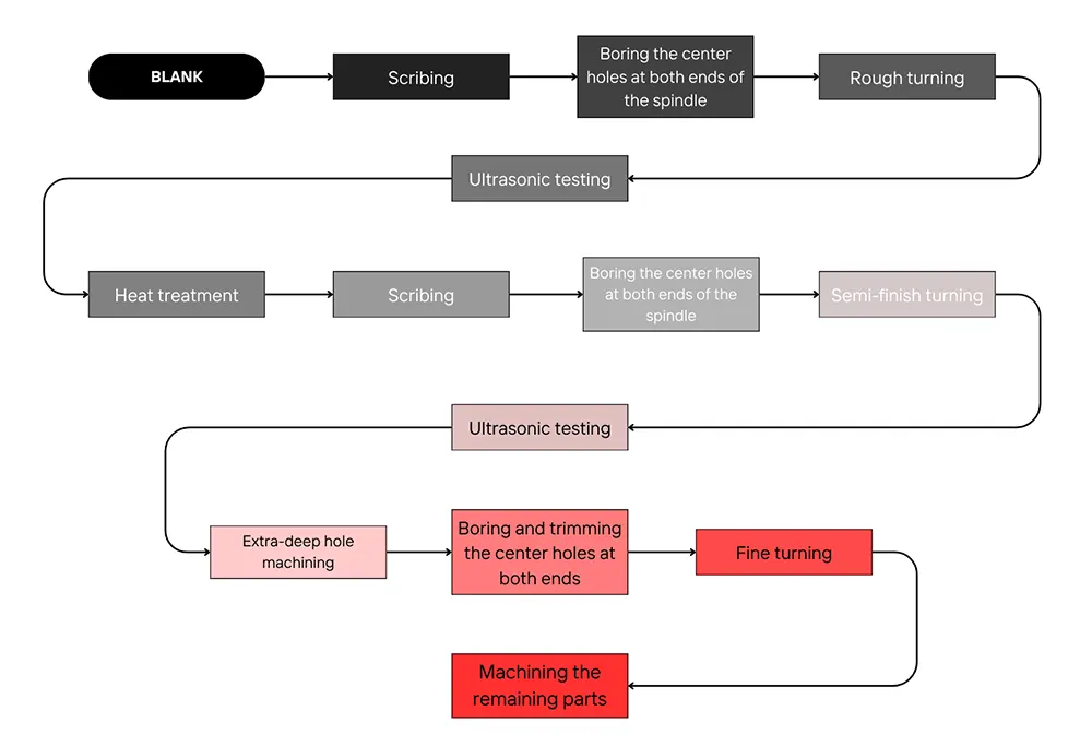
Figure 2 shows the final large spindle machining process flow.
Figure 2 Large spindle machining process flow
Process Testing
Selection of Machining Equipment
Based on the requirements for ultra-deep hole machining of large spindles, engineers select a CNC deep hole drilling and boring machine with high rigidity and precision.
Its drilling diameter range is 35–150 mm, with a maximum drilling depth of 15,000 mm, capable of meeting the ultra-deep hole machining needs of spindles of various specifications.
Machinists select a 42CrMo, φ40 mm drill rod to machine the through-hole in the spindle core.
Since the through-hole in the spindle core requires a machining length of 6,560 mm, engineers select an 8,000 mm drill rod. This ensures they can machine the through-hole in one pass from a single end.
The machining method involves rotating the workpiece while the drill bit rotates in the opposite direction to ensure good straightness of the machined workpiece.
Tool Selection
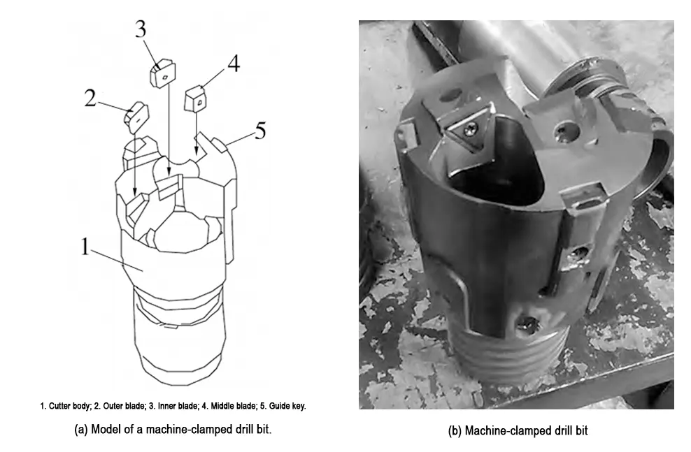
Machinists use a φ45 mm machine-mounted drill bit to conduct ultra-deep hole machining tests on the spindle.
Based on previous deep hole machining experience, engineers use spray-suction drills and BTA drills for internal chip removal. They apply these tools in deep hole machining.
Before the test, machinists pre-bore a guide hole with a diameter of 45 mm at the shaft end.
The depth of the guide hole exceeds the distance from the front end of the machine-mounted drill bit to the drill rod, allowing the drill rod to fully enter the hole.
The guide hole is coaxial with the machine tool spindle centerline, and its bottom surface is flat.
A flat bottom surface not only facilitates the formation of an ideal chip shape but also ensures uniform force distribution on the cutting edge.
Otherwise, the asymmetric arrangement of the drill bit inserts will cause unbalanced cutting forces, resulting in severe cutting vibrations; the inserts are prone to damage and may form long chips that block the chip evacuation channels, hindering chip removal.
The machine-mounted drill bit is illustrated in Figure 3.

Setting of Machining Parameters
The machining parameters for deep hole drilling are critical to the successful completion of ultra-deep hole machining, and their determination requires comprehensive consideration of multiple factors.
(1) Technical Parameters:
Based on the rated parameters of the machining equipment and combined with previous machining experience, the coolant flow rate is preliminarily set before trial cutting, and adjusted promptly according to the actual chip removal situation.
(2) Cutting Parameters:
The selection of cutting parameters is closely related to the strength of the cutting insert, the diameter and length of the drill rod, as well as the material being machined and its hardness.
Excessively high spindle speeds can increase drill rod oscillation and cause severe vibration; different materials and hardness levels require different cutting parameters.
Before commencing drilling, operators can only preliminarily determine cutting parameters based on experience for trial cutting.
They then make further adjustments according to chip removal patterns until they establish the optimal cutting parameters.
When the cooling system pressure is set to a constant value of 4 MPa, with a coolant flow rate of 180 L/min, spindle speed of 100 r/min, and feed rate of 6 mm/min, the large-spindle deep-hole drill achieves smooth chip removal. It also maintains a stable drilling process.
After inspection, the surface roughness of the deep hole reached Ra12.5.
The coaxiality with the outer diameter was controlled within 1 mm. These results indicate that the processing parameters meet the required standards.
Conclusion
Through research on the deep hole drilling process for large spindles, engineers have resolved issues such as hole deviation, tool vibration, wear, and difficulties in chip removal.
After processing, all performance indicators of the spindle meet the required standards.
This process can guide the manufacturing of large spindles.
FAQ
What is ultra-deep hole machining, and why is it essential for large spindles?
Ultra-deep hole machining creates long, precise holes in large spindles, reducing weight, improving material utilization, and meeting special structural requirements.
How do hollow shafts compare to solid shafts in torque and bending performance?
Comparative studies show that hollow shafts and solid shafts with the same outer diameter have minimal differences in transmitting torque, bending moments, and combined bending-torsion forces.
Why are hollow shafts preferred for large spindle components?
Hollow shafts significantly reduce shaft mass while maintaining strength, making them ideal for heavy equipment applications requiring ultra-deep holes.
What is the current demand for ultra-deep hole machining in the mechanical manufacturing industry?
Statistics indicate that over one-third of the mechanical manufacturing industry requires ultra-deep hole machining technology and the supporting equipment to meet production needs.
Which deep hole machining technologies are used for small versus large diameters?
Gun drilling is effective for holes under 20 mm in diameter and 1,500 mm in length. Spray-suction and BTA drills handle diameters of 25–30 mm for lengths below 3,000 mm, while ultra-deep holes in large spindles (3,000–7,000 mm) require specialized equipment.
What are the main challenges in ultra-deep hole machining of large spindles?
Operators cannot directly observe cutting conditions, and the long cutting path can cause hole deviation, tool vibration, wear, and chip removal difficulties, impacting quality and efficiency.
How is coaxiality ensured between the through-hole and outer diameter in large spindles?
Machinists reserve allowance on the outer diameter, align the part using the through-hole as a reference, and finish-machine the outer circumference on CNC lathes to maintain coaxiality within 1 mm.
Which equipment and tools are best for large-spindle ultra-deep hole machining?
A CNC deep hole drilling and boring machine with high rigidity and precision is used, along with drill rods such as φ40 mm 42CrMo rods and φ45 mm machine-mounted drill bits, supported by spray-suction or BTA drills for chip removal.
How are machining parameters optimized for ultra-deep hole drilling?
Operators first set preliminary cutting parameters based on experience and trial cuts, then adjust according to chip removal patterns. Cooling system pressure, coolant flow, spindle speed, and feed rate are all critical to achieving smooth drilling and maintaining stability.
What results indicate successful ultra-deep hole machining of large spindles?
Successful machining is indicated by surface roughness reaching Ra12.5, coaxiality with the outer diameter controlled within 1 mm, and the elimination of issues like hole deviation, tool vibration, wear, and chip removal difficulties.


