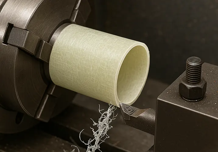
With the development of industrial technology, more and more new materials with thin walls have been applied in industrial production on a large scale, which significantly improves product performance and reduces product costs.
Glass fiber reinforced plastic material has high strength, light weight, good insulation, and corrosion resistance,
which are its performance advantages.
Among many materials, it has outstanding performance and is popular. However, it is difficult to cut due to its wear-resistant machining characteristics.
This makes it easy to cause tool wear and machining vibration, which affects the surface quality. To a certain extent, this restricts the popularity and development of the material.
It belongs to the typical category of difficult-to-cut composite materials.
Problems and analysis in machining
Description
Figure 1 shows a thin-walled FRP part, which is a glass fiber reinforced plastic composite material, with the external dimensions of φ400mm × 9000mm, tubular rotary body, and a wall thickness of 2mm.
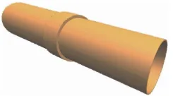
When turning thin-walled FRP parts at the outer circle position,
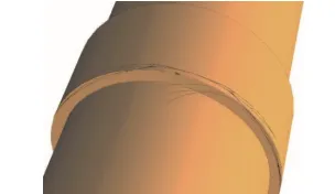
there are tearing, slagging, cracks, and burr defects at the intersection of the end face of the discharge tool and the outer circle.
At the same time, the surface roughness of the outer circle is poor.
There will also be frequent machining vibrations, which affect the surface machining quality of thin-walled parts, tool life, and machining efficiency.
The defects in glass fiber reinforced plastic parts are shown in Figure 2.
Analysis
(1) tool material selection
Tool material selection is unreasonable FRP is a composite hard-to-cut material, high tensile strength of the material, low thermal conductivity, high cutting temperature and tool life is short, the material is easy to cause tool wear, which leads to processing vibration, affecting the surface roughness, the size is not easy to ensure.
(2) The selection of cutting parameters is unreasonable.
FRP is a non-homogeneous material with interlayer organization and fiber directionality.
Between the layers, delamination is likely to occur. During the processing, this can lead to collapse, slag, and other defects.
Due to the small connection force during processing, it is very easy for the cutting parameters to be selected improperly.
This can result in excessive cutting force on the tool. As a result, the cutting heat becomes too high, which causes the glass fiber to lift up, leading to slagging.
When the cutting tool cuts the workpiece, the feed speed is not decelerated. As a result, the tool leaves the workpiece at a fast speed.
In a split second, this drives the chip, causing tearing. This triggers cracks, slagging, and other phenomena.
(3) Cutting path setting
The cutting path setting is unreasonable, and the fiber elasticity recovery phenomenon occurs during the processing of FRP materials.
This makes it difficult to control processing accuracy and surface roughness. When the 90° external circle right offset lathe cuts the outer circle, the FRP material rebounds.
At the moment of cutting, the lathe vice’s rear blade surface and the vice cutting edge come into contact with the workpiece’s outer circle at the knife end face.
This contact results in strong cutting forces, which generate cracks and slag.
(4)The incoming material state is not uniform.
Artificially wound fiberglass parts have irregular shapes and inner holes.
Each diameter is different, and the cylindricity is poor. There is uneven allowance, which results in more empty knife cutting during turning.
Irregular intermittent impact cutting easily generates processing vibration, which increases cutting difficulty.
This vibration shortens tool life. Additionally, if the feed rate remains constant without adjusting or optimizing the cutting parameters based on the actual situation,
the cutting time becomes longer, which negatively affects processing efficiency.
Tool improvement and response program
Optimization of tool material
For the characteristics of FRP material and the state of the blank, turning adopts a combination of roughing and finishing mode.
For rough machining of FRP materials, high-speed steel and small geometric angle uncoated carbide tools experience more serious wear and should not be selected.
Instead, tools with a larger geometric angle should be chosen.
The front angle should be between 10° and 20°, the back angle between 6° and 8°, and the edge tilt angle between 3° and 5°.
The tool should also have a polished groove and a coating, such as TiN, TiCN, or Al₂O₃.
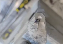
YG class negative indexable inserts (see Figure 3) are a good choice.
These inserts feature sharp grooves, fast cutting, efficient chip removal, and can handle very high cutting speeds.
YG negative indexable inserts (see Fig. 3) have sharp grooves, enabling fast cutting and smooth chip removal.
These inserts are also economically beneficial. They effectively reduce friction between the chips and the front face.
This ensures stability during both the cut-in and cut-out processes. Additionally, the inserts reduce bonding between the chips and the front face.
As a result, higher surface quality is achieved, and the insert life is extended.
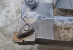
For finishing, it is appropriate to use diamond turning inserts or cubic boron nitride tools, as shown in Figure 4.
These tools have high hardness and heat resistance, making them sharper and more durable than steel tools.
The friction is reduced, and the chips are crushed into C-shaped flakes. This prevents tearing and pulling of the workpiece.
Additionally, vibration is reduced, and cutting parameters are significantly improved.
As a result, higher machining accuracy and productivity are achieved. Higher machining accuracy and production efficiency can be achieved.
Optimization of the machining tool path
The design of the machining tool path should ensure that when the machining tool cuts out the end face of the workpiece, the workpiece’s allowance and cutting force are gradually reduced to avoid the cutting force disappearing instantly.
According to the machining characteristics of the outer circle of the part, the type of tool selected and other actual conditions, the following three ways to design and optimize the machining tool path.
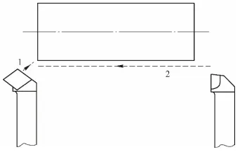
1) The tool path for the 45° and 90° offset tool composite machining is shown in Figure 5.
First, the 45° offset tool cuts out the end and creates a cylindrical 45° chamfer with a depth greater than 1.1 times the original amount.
Next, the CNC machining program for the 90° offset tool is divided into two segments.
The first segment begins about 5mm from the cut-out end of the workpiece.
The feed amount is set to half of the original value to reduce cutting force at the end.
This adjustment helps prevent chipping, slagging, and delamination caused by the tool and workpiece separating during machining.
2) The connection force at the end of the fiberglass is small, making it prone to separation due to external forces.
To address this, the turning tool can be fed from the outside to the inside.
Using the left and right composite offset machining method helps to prevent chipping and cracking at the end caused by tearing.
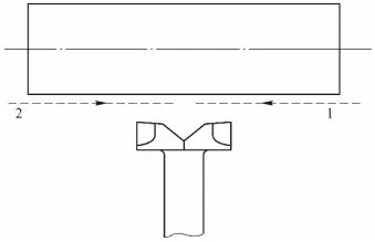
A 90° left and right composite offset tool was designed and produced. The tool’s processing path is shown in Figure 6.
The machining begins by feeding from the two end faces toward the center for cylindrical turning.
The left cylindrical turning tool is used to perform reverse-direction turning for a length of about 30mm.
After that, the right cylindrical turning tool is used for normal turning.
Since the allowance at the exit tool has already been removed in advance, this approach prevents tearing, slagging, and cracking at the end face where the tool exits.
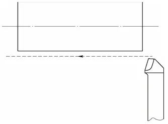
3) The tool path for the 45° to 75° turning tool machining is shown in Figure 7.
The main offset angle for the turning tool ranges from 45° to 75° when processing the parts.
The turning tool should quickly cut out the end face. The feed rate should be reduced accordingly during this process.
Optimization of cutting parameters
In the processing of FRP materials, cutting parameters are important factors affecting cutting efficiency, machining quality and tool wear.
To reduce cutting heat and cutting force, the cutting speed, feed rate, and back draft should be properly controlled and kept within reasonable limits.
These parameters should not be set too high. During roughing, it is advisable to use a lower cutting speed along with a relatively larger feed rate and back draft.
This approach helps shorten cutting time and reduces tool wear.
For finishing, a higher cutting speed can be used in combination with a smaller feed rate and back draft.
This ensures better surface quality and machining precision. In order to ensure product quality, to avoid surface roughness does not meet the requirements of the drawing, it should be noted that the processing should be timely check the tool wear, timely replacement, cutting parameters in Table 1.

> Managing Material Variability and Air Cutting
When the incoming material state is not uniform, it may result in air cutting, which affects machining efficiency.
To address this, the operator can manually adjust the transverse and longitudinal cutter entry points based on the condition of the incoming blanks.
By using a larger back draft and feeding quickly to the high point of the blank, the cutting tool can reach the effective cutting position sooner.
This helps reduce unnecessary air cutting and improves overall efficiency. When machining vibration occurs, manual intervention can be applied based on the actual situation.
This involves adjusting the cutting parameters in real time. By continuously changing the feed rate and adjusting the feed multiplier, the excitation frequency of the workpiece can be altered.
These adjustments help to reduce the vibration of the workpiece during processing. If necessary, vibration-damping materials can be filled into the inner hole of the part.
These materials may include low-temperature alloys, wax, sand, or iron sand. Additionally, in the non-machining areas of the outer surface of the workpiece, bundled sandbags can be applied using rope hoops, clamps, hoops, steel ties, or plastic ties.
These methods help achieve better vibration damping and absorption, thereby enhancing cutting stability.
Optimization of cooling mode
Cutting heat has a great impact on the processing of FRP materials, mainly including four aspects:
① Cutting heat will aggravate tool wear, shorten tool life.
② It is easy to make the workpiece produce thermal deformation, affecting the geometric tolerance and dimensional accuracy of the parts.
③ Chips and tool front surface of the tool is easy to occur bonding, resulting in parts surface roughness does not meet the requirements.
④ accelerate the decomposition of glass fiber at high temperature, resulting in the occurrence of defects such as slagging, cracks and burrs on the end face of the parts.
> Importance of Cooling and Lubrication
Therefore, should be used both good cooling and lubricating cutting fluid, at the same time, the appropriate cooling method is also very important.
Water-based cutting fluid is preferred in the machining process. It can effectively reduce the temperature in the cutting area between the tool and the workpiece.
At the same time, it helps to flush away accumulated chips in a timely manner. This achieves rapid cooling and makes the machining process smoother and more efficient.
The cutting fluid should be kept fully and continuously poured during the machining process to ensure that the temperature of the machining process is stable.
> Limitations of Oil-Based and Gas Cooling
Avoid the use of oil-based cutting fluid and pure gas for cooling, oil-based cutting fluid in the chemical substances can easily and FRP material chemical reaction, reduce or change the comprehensive performance of the parts.
Pure gas cooling works by blowing high-pressure gas onto the workpiece processing area to achieve cooling.
However, this process causes chips and dust to be scattered into the air by the high-pressure gas.
This not only seriously affects environmental hygiene but also poses risks to the operator’s physical health.
In addition, it accelerates equipment wear and tear, ultimately reducing the overall accuracy of the equipment.
Processing Precautions
Since the processing of thin-walled FRP parts generates a large amount of fine dust and fibers, there is a potential risk to human health.
Therefore, operators must wear appropriate personal protective equipment, such as dust masks, protective gloves, and safety glasses.
In addition, dust-absorbing equipment should be used to keep the working environment clean.
This also helps prevent dust from entering the internal motion mechanisms of the equipment.
In addition, there may be a risk of fire and explosion during the machining process.
The resulting chips should not be allowed to accumulate and must be cleaned up promptly using appropriate methods.
The equipment must also be equipped with an effective chip removal system and proper ventilation devices to ensure safety.
In summary, technicians should fully understand and master the processing characteristics of FRP materials, and take necessary safety measures to ensure the safety of processing production and operators.
Through process improvements, an effective solution was developed to address common defects in the turning of thin-walled FRP parts, such as slag, cracks, and burrs.
These improvements enhance the surface machining quality and overall dimensional accuracy of the parts.
As a result, the processed parts meet the required process standards.
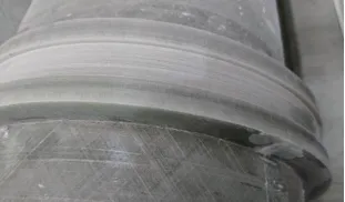
The machining results are shown in Figure 8.
 Health Hazards of Machining Fiberglass
When machining fiberglass, fine glass fibers and resin dust are released into the air. Here’s what can go wrong:
1. Respiratory Problems
Inhaled fiberglass dust can:
Irritate the nose, throat, and lungs
Cause chronic coughing, wheezing
Lead to chronic bronchitis or other lung damage over time
Dust masks or respirators (N95 or higher) are essential.
2. Skin Irritation
Glass fibers can penetrate the skin and cause:
Itching
Rashes
Redness or swelling
Wear long sleeves, gloves, and protective clothing.
3. Eye Irritation
Dust in the air can:
Irritate or scratch the eyes
Cause redness and tearing
Always wear safety goggles.
4. Toxic Resin Fumes
If the resin in the fiberglass contains harmful additives, cutting it can release:
Volatile organic compounds (VOCs)
Formaldehyde
Make sure there’s good ventilation and use fume extraction if needed.
Conclusion
aking the turning processing of thin-walled glass fiber reinforced plastic (FRP) parts as an example, this study addresses common defects such as poor surface roughness and machining vibration.
To resolve these issues, preferred tool selection, optimized tool path planning, and appropriate adjustment of cutting parameters were implemented.
Through these methods, effective strategies were summarized to avoid defects during the turning of thin-walled FRP parts.
The proposed techniques significantly improve the surface quality of the parts, extend tool life, and enhance machining efficiency.
These findings provide valuable reference for the processing of other FRP components and are worth promoting in similar applications.
FAQ
What is a CNC milling cutter?
A CNC milling cutter is a precision cutting tool used in CNC milling machines to remove material from a workpiece, shaping it into the desired form.
What types of CNC milling cutters are available?
Common types include end mills, face mills, ball nose cutters, slab mills, and T-slot cutters, each suited for specific machining operations.
How do cutter materials affect machining performance?
Cutter materials such as high-speed steel (HSS), carbide, and ceramic influence cutting speed, durability, heat resistance, and the ability to machine different materials.
What are the main applications of CNC milling cutters?
They are used for planar milling, contour milling, cavity milling, slotting, profiling, and creating complex 3D surfaces.
How does cutter geometry impact machining quality?
The geometry—including flute design, helix angle, and cutting edge sharpness—affects chip evacuation, surface finish, and tool life.
How do you select the right CNC milling cutter for a job?
Selection depends on the workpiece material, required surface finish, machining speed, depth of cut, and production volume.
Why are cutting parameters important in CNC milling?
Parameters such as spindle speed, feed rate, and depth of cut determine efficiency, tool wear, and surface quality.
How often should CNC milling cutters be replaced?
Replacement frequency depends on usage intensity, material hardness, and proper maintenance, but regular inspection helps prevent tool failure.
What maintenance practices extend cutter life?
Proper storage, regular cleaning, correct coolant use, and avoiding excessive cutting loads help extend tool longevity.
Can CNC milling cutters be re-sharpened?
Yes, many milling cutters, especially carbide and HSS tools, can be re-sharpened to restore cutting efficiency and reduce costs.

