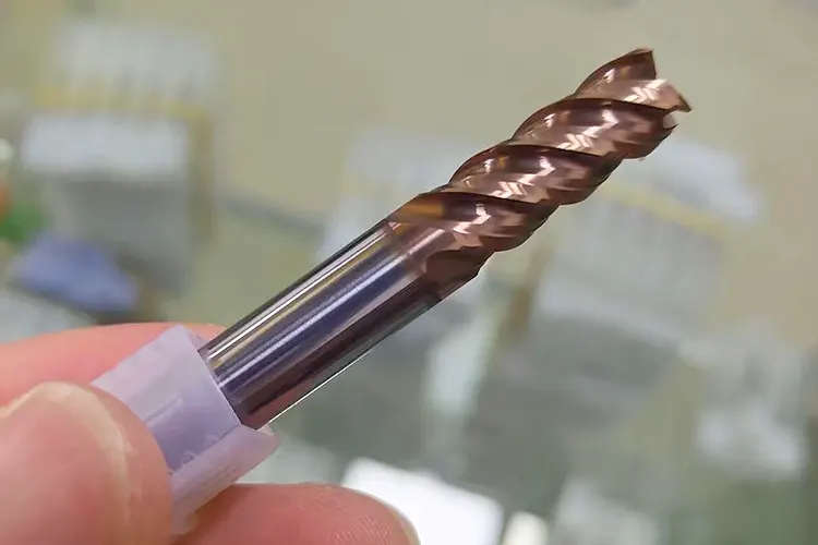
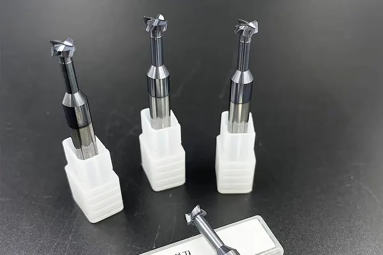
CNC milling cutter, as the direct cutting tools applied to workpieces, come in a wide variety of types. Different tool structures and materials exhibit distinct cutting performance characteristics.
These characteristics allow manufacturers to use them for various machining tasks, including planar milling, contour milling, and cavity milling.
Meanwhile, cutting parameters serve as the “pace regulator” in the machining process.
When engineers properly set the cutting speed, feed rate, and cutting depth, they ensure the workpiece meets the required precision and surface quality.
These optimized settings also maximize the machine tool’s performance, prevent excessive tool wear or damage, and help reduce processing time and costs.
Therefore, thoroughly considering the selection of CNC milling tools and cutting parameters is crucial for optimizing the application of CNC milling technology.

Requirements for tools in CNC milling
Select tools with good rigidity
In CNC milling, tool rigidity is of utmost importance.
Rigid tools allow operators to fully harness the machine tool’s performance. They support high-allowance cutting, which boosts production efficiency.
In addition, rigid tools help prevent vibrations in the machining system, ensuring both accuracy and surface quality.
When tools lack sufficient rigidity, machinists can manually adjust uneven allowances through layered cutting.
However, CNC milling relies on pre-written programs, which limit such flexible adjustments.
Excessive allowances may cause tool breakage, while using smaller allowances to prevent breakage may result in excessive idle cutting and conservative cutting parameters, leading to low efficiency.
When tool rigidity is sufficient, there is no need to worry about uneven allowances, enabling CNC milling to proceed more smoothly and efficiently, thereby effectively advancing the machining process.
Select tools with high wear resistance
When tool durability is low, the wear rate of the tool during machining significantly accelerates.
Changes in tool condition directly affect workpiece processing accuracy. Tool wear increases cutting force, leading to part deformation beyond tolerance limits.
Additionally, during tool changes, alignment errors can result in surface marks, adversely affecting surface quality and processing accuracy.
Furthermore, increased tool change and tool alignment frequencies reduce effective machining time, accelerate tool wear, impact machine tool utilization rates, and increase production costs.
Select high-quality tools
CNC machine tools feature automatic continuous machining and high-speed operation.
However, manufacturers cannot fully realize the efficient machining potential of CNC machine tools unless they use high-quality CNC tools precisely matched to these capabilities.
Taking the widely adopted high-speed machining centers in the manufacturing industry as an example, during machining operations, the tool’s linear speed can reach extremely high levels.
In such cases, if the tool’s red hardness and wear resistance are inadequate, the tool will wear out at an extremely fast rate, thereby failing to effectively ensure the required machining accuracy of the parts.
Conversely, if operators use lower cutting speed parameters, they fail to take full advantage of high-speed cutting technology.
Selection of CNC Milling Tools
Selection of Milling Tools
Machinists typically select embedded disc-type milling cutters to machine large flat surfaces.
This is primarily due to their larger tool diameter, which reduces the frequency of repeated tool passes, enhances milling efficiency, avoids indirect tool marks between tool paths, and optimizes surface quality.
For small surfaces, bosses, stepped surfaces, and side contours, cylindrical milling cutters are more suitable.
Keyway milling cutters with over-center cutting capability are more suitable for machining tasks involving closed recesses such as keyways and waist-shaped slots.
Two-flute keyway milling cutters, with their relatively spacious chip clearance space, are suitable for heavy-duty machining scenarios, ensuring that the machined dimensions of the slot meet precision requirements.
Machinists use ball-nose cutters for specific curved surface machining tasks. These cutters help avoid interference and overcutting between the tool tip and the workpiece surface.
As a result, they ensure high precision and quality in curved surface machining.
Selection of hole machining tools
In hole machining operations, the primary task is to precisely move the spindle or worktable for positioning to ensure accurate hole locations.
Twist drills rely on the drill core for connection, which reduces their rigidity. This structure makes it hard for coolant to reach the cutting area during drilling.
As a result, the drill generates excessive heat and fails to remove chips efficiently. This can cause the hole to deviate from its intended path.
To prevent this, machinists should control the drill depth-to-diameter ratio within 5. Pre-drilling a center hole with a center drill before drilling can meet positioning accuracy requirements.
> Tool Strategies for Reaming and Boring
Before precision reaming, chamfering the hole opening facilitates reamer guidance. Machinists should select a floating reamer to eliminate reaming position deviations.
When boring, multi-edge boring tools can balance boring forces and suppress vibrations. Machinists should use a short, thick tool shank.
> Optimizing Tool Selection and Machining Sequence
If interference occurs, only remove material from the interfering area to enhance rigidity, ensuring hole dimensions and surface quality.
The selection of hole processing methods is equally critical and must adhere to a series of principles. First, engineers should consolidate tool types to reduce the total number.
When machining, after selecting a tool, it is advisable to complete all machining tasks for that tool in a single operation.
Engineers should distinguish between roughing and finishing tools. Although this approach may increase the number of tools used, it reduces wear on finishing tools and ensures part accuracy.
After milling a flat surface, process the holes on that surface to avoid drilling slippage.
If the operation involves both curved surfaces and side contours, machinists should first finish the curved surfaces and then process the contours. They should choose tools with excellent durability, hardness, and wear resistance.
Although the surface cost may appear higher at first, engineers often accept this trade-off. By allowing longer cutting times and maintaining better precision, they improve processing quality and efficiency.
This approach also reduces interruptions during machining and, when evaluated as a whole, significantly lowers overall production costs.
The reasonable selection of hole processing tools and methods is a core element for achieving efficient and high-precision hole processing.
Manufacturers rely on it to optimize the entire machining process and enhance product quality.
It also offers strong technical support and ensures effective cost control, helping enterprises stay competitive in a demanding market.
Other tool selection
Other tools used in CNC milling play a crucial role in expanding the functionality of milling machines and enhancing their adaptability to different workpieces.
When selecting other tools, the following aspects should be prioritized:
First, ensuring tool precision is of utmost importance.
Second, tools with good durability should be prioritized.
During prolonged machining, both the surface and internal structure of the tool will sustain some degree of damage.
When the tool’s outer surface becomes damaged, it loses machining performance. Operators may notice reduced accuracy and slower cutting speeds.
If the internal structure fails, the tool may break entirely, potentially damaging both the workpiece and the milling machine.
However, when tools are selected appropriately, the probability of internal structural damage leading to breakage is relatively low.
Finally, tools should be inspected regularly and replaced as needed, and appropriate adjustments should be made after replacement to ensure that machining operations can proceed smoothly and orderly.
Determination of cutting parameters for CNC milling
Determination of cutting speed
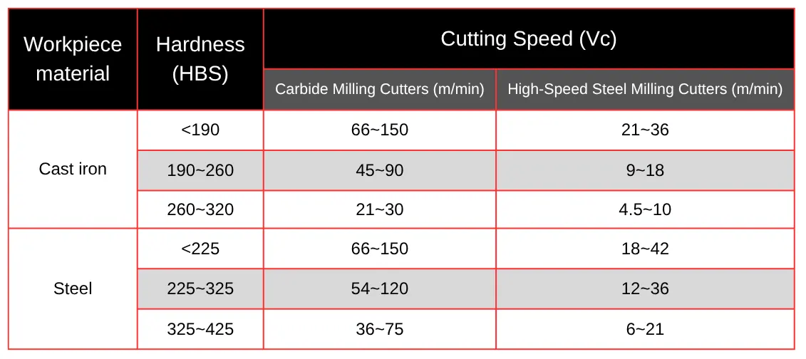
Cutting speed is inversely proportional to tool durability T, back cutting depth ap, side cutting depth a, number of teeth Z, and feed rate per tooth fz, and directly proportional to the diameter d of the milling cutter.
When machinists increase the back cutting depth (ap), side cutting depth (ae), number of teeth (Z), and feed rate per tooth (fz), more teeth engage in the cutting process.
This change increases the load on each cutting edge. This results in more cutting heat in the cutting zone, raising the temperature and accelerating tool wear.
Therefore, when determining the cutting speed, it is necessary to consider tool durability.
For large-diameter milling cutters, which have more favorable heat dissipation conditions, higher cutting speeds can be considered.
As shown in Table 1, reference values for cutting speeds are listed for steel and cast iron materials under different material hardness conditions during milling operations.

Determining the cutting depth
In CNC milling, differences in machine tool types and processed materials can affect the selection of cutting depth, so matching the cutting depth with the machine tool and material is critical.
When determining the cutting depth, it is essential to consider the actual machining environment.
During rough machining, operators increase the cutting depth when the tool stiffness meets the requirements. This allows them to remove more material in a single pass and improve efficiency.
However, if the tool lacks sufficient stiffness or the material is too thick, increasing the cutting depth may cause abnormal cutting or prevent the tool from cutting through the material. These issues hinder the machining process.
During cutting, to prevent tool edges from damaging machine tool metal components, the tool edges should be oriented inward to avoid contact with metal objects.
When tool stiffness is low and the material is thick, subjected to large impact loads, the cutting depth should be reduced to improve cutting quality and reduce the risk of tool damage.
When determining the cutting depth, the machining allowance should also be considered.
Precisely controlling the allowance and appropriately reducing the depth can reduce resource waste, improve machining quality, and enhance efficiency.
Under normal circumstances, the cutting depth should be between 0.05 mm and 1.0 mm. For semi-finishing, it is recommended to control it between 1 mm and 3 mm.
Operators adjust the cutting depth flexibly within the appropriate range according to processing requirements. This practice helps them achieve optimal results and maintain smooth CNC milling operations.
It also ensures processing accuracy, meets the demands of various tasks, and optimizes the overall workflow.
Determining Feed Rate
Feed rate F is a key factor influencing CNC machining efficiency.
Its value must be determined by considering multiple factors, such as tool material properties, workpiece material machining performance, and machining allowance conditions.
When machining part contours, cutting forces may suddenly change at specific locations, potentially damaging the tool.
When the tool approaches a corner or encounters a sudden change in cutting allowance, the feed rate is typically reduced appropriately to prevent overcutting or undercutting of the part contour corners.
Feed rate settings follow the following principles:
First, under the premise of ensuring the processing quality of the workpiece, it is advisable to select a higher feed rate to improve efficiency.
During conventional cutting operations, the feed rate typically ranges from 100 mm/min to 200 mm/min.
Second, when using a saw blade to cut parts or perform deep hole machining, due to the special nature of the process, it is recommended to use a lower feed rate, typically ranging from 20 mm/min to 50 mm/min.
Third, when the machining accuracy requirements are at a high level and there are strict limitations on surface quality, a relatively smaller feed rate value should be selected within the range of 20 mm/min to 50 mm/min.
Finally, operators set the feed rate during the tool’s idle feed state based on the maximum idle feed speed parameter programmed into the CNC system.
This setting ensures precise and coordinated tool movements throughout the machining process.
It also meets the specific speed control needs of various machining stages, thereby guaranteeing the high-quality completion of part machining.
These principles work together to help reasonably determine the feed rate in different machining scenarios, ensuring the smooth progress of CNC milling and the achievement of machining quality.
Determination of back cutting depth
Under the premise that the surface roughness of the part meets the relevant requirements, the selection of back cutting depth should comprehensively consider the part’s process rigidity, machine tool, fixture, and tool.
Under conditions where the process system’s rigidity permits, to improve processing efficiency, it is recommended to use a larger back cutting depth to reduce the number of passes.
When the surface roughness requirement is approximately Ra 3.2 μm to 12.5 μm, the processing should be performed in two stages: rough milling and semi-finishing milling.
The allowance left after rough milling should be 0.5 mm to 1.0 mm; When the surface roughness requirement is Ra 0.8 μm to 3.2 μm, the process should include rough milling, semi-finishing milling, and finishing milling.
During semi-finishing milling, operators set the depth of cut for both end milling and side milling between 1.5 mm and 2 mm.
During finishing milling, they reduce the depth of cut to between 0.5 mm and 1 mm. For peripheral milling, they set the side milling depth of cut between 0.3 mm and 0.5 mm.
Conclusion
The reasonable selection of CNC milling tools and cutting parameters is the key to achieving high-quality and efficient CNC milling.
Engineers carefully select tools and cutting parameters to improve part processing accuracy and reduce surface roughness.
This practice ensures products meet strict quality standards. It also allows operators to fully utilize the machine tool’s maximum efficiency, reduce tool wear, save costs, and boost corporate competitiveness.
FAQ
What types of CNC milling cutters are available and how do their structures affect machining?
CNC milling cutters come in various types, each with different tool structures and materials. These differences influence cutting performance, making certain tools better suited for tasks like planar milling, contour milling, or cavity milling.
Why is tool rigidity important in CNC milling?
Tool rigidity allows operators to maximize machine tool performance by supporting high-allowance cutting and preventing vibrations, which ensures machining accuracy and surface quality.
How do cutting parameters impact CNC milling efficiency and product quality?
Properly setting cutting speed, feed rate, and cutting depth helps achieve required precision and surface finish, reduces tool wear, and enhances machine performance, ultimately lowering processing time and costs.
What factors should be considered when selecting CNC milling tools?
Manufacturers should prioritize tool rigidity, wear resistance, and quality to fully utilize CNC machines’ capabilities and maintain machining accuracy at high speeds.
How do you select the appropriate milling cutter for different surface types?
For large flat surfaces, embedded disc-type milling cutters are preferred due to their efficiency and surface finish, while cylindrical cutters suit small surfaces and contours. Ball-nose cutters are ideal for curved surface machining.
What are best practices for hole machining tool selection?
Precise spindle or worktable positioning is crucial. Tools like twist drills, center drills, floating reamers, and multi-edge boring tools should be selected carefully to balance rigidity, heat dissipation, and vibration suppression.
How should cutting speed be determined in CNC milling?
Cutting speed depends on tool durability, cutter diameter, cutting depths, number of teeth, and feed per tooth. Larger tools with better heat dissipation can handle higher speeds to improve efficiency.
What is the recommended approach to determining cutting depth in CNC milling?
Operators should match cutting depth to tool stiffness, machine type, and material. Proper depth improves efficiency and prevents issues like tool breakage or abnormal cutting, with typical depths ranging from 0.05 mm to 3 mm depending on the machining stage.
How does feed rate influence CNC milling operations?
Feed rate affects machining efficiency and quality. Higher feed rates increase productivity but require careful adjustment near corners or contours to avoid defects. Idle feed rates must follow CNC system parameters for coordinated tool movement.
Why is distinguishing between roughing and finishing tools beneficial?
Separating roughing and finishing tools reduces wear on finishing tools, preserves part accuracy, and balances tool usage, even if it increases the total number of tools used.

