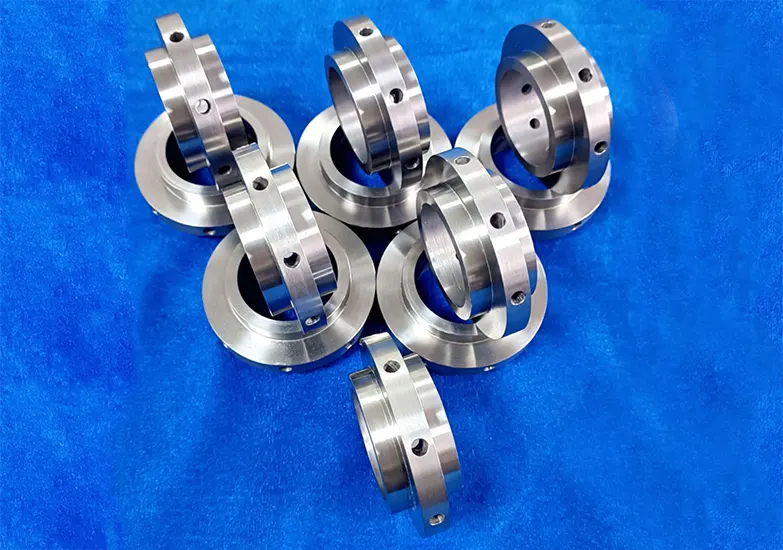
Titanium alloys, due to their unique properties, are widely used as component materials in the aerospace industry.
However, their high hardness and poor machinability classify them as difficult-to-machine materials.
During processing, surface hardening of the components is prone to occur, posing significant challenges for mechanical machining.
Tool Material and Geometry
The tool materials typically used for machining titanium alloys require high hardness and wear resistance, as well as excellent thermal stability, maintaining high strength, toughness, and resistance to impact and damage at high temperatures.
Tools that meet these requirements include ceramic tools, coated carbide tools, cubic boron nitride (CBN) tools, and diamond (PCD) tools.
Among these, coated carbide tools are cost-effective and offer good thermal conductivity and high hardness.
Although their thermal stability and chemical stability are inferior to those of ceramic tools, cubic boron nitride tools, and diamond-like tools, their superior impact resistance and fracture resistance make them the preferred choice for machining titanium alloys.
When selecting tool geometry angles, the following requirements must be met: a small front angle, a negative rake angle with a chamfer, a large main rake angle, and a large clearance angle.
Optimization and Application of Cutting Parameters for Titanium Alloy Materials
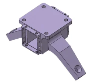
The material of the part shown in Figure 1 is TC11 titanium alloy, with the cantilever and joint forming an integrated structure.
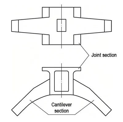
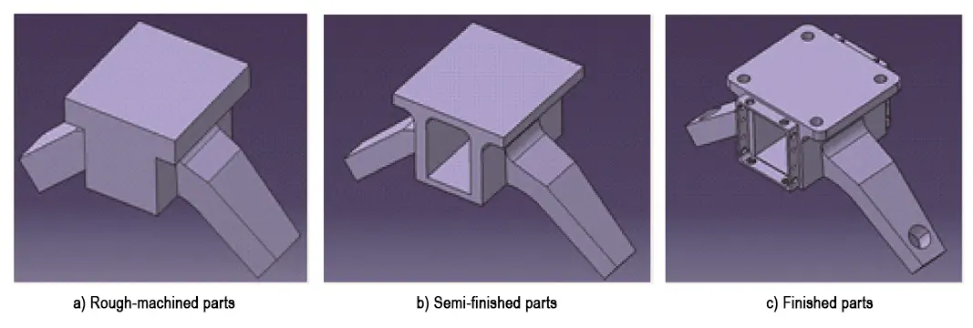
The part is divided into sections as shown in Figure 2, and the machining process is illustrated in Figure 3.
The machining challenges are as follows:
1) The blank is a heavy-duty free-forged part with a hardened surface layer, irregular shape, and a material removal rate exceeding 80% after machining, resulting in large machining allowances and high difficulty.
2) The intermediate slot cavity is deep, approximately 400 mm, and requires high dimensional accuracy. Unreasonable cutting parameters during machining cannot ensure dimensional accuracy.
3) The overhang of the cantilever section exceeds 600 mm. Unreasonable cutting parameters during machining can cause vibrations, affecting the surface quality of the part.
4) Since this is the first time machining TC11 titanium alloy material, the types and quantities of tools available for machining such materials are limited.
Additionally, considering that new tools would increase machining costs, it is difficult to set finishing cutting parameters during machining, resulting in low tool life and machining efficiency during the initial roughing stage.
TC11 titanium alloy is a difficult-to-machine material. To address this challenge, we studied the machining properties of titanium alloys in detail.
We then analyzed the part’s structural characteristics and considered the high material removal rate.
Based on this analysis, we optimized the cutting process from three key aspects: tool selection, machining strategy, and machining parameters..
Tool Selection
Considering the machining characteristics of titanium alloys, coated carbide indexable end mills are the preferred choice for machining titanium alloy materials, effectively removing the majority of machining allowances.
Due to the presence of a hardened layer on the surface of the parts, which significantly affects tool life, selecting the appropriate coated tools is particularly important and has the greatest impact on tool costs.
Why Coating Technology Matters in Tool Performance
In strategies to enhance tool performance, coating technology plays an indispensable role.
Tool coatings act like a sturdy and precise “armor” for the tools, significantly enhancing their wear resistance, heat resistance, and corrosion resistance during the cutting process.
Currently, advanced coating processes are constantly emerging, with common coating materials including diamond-like carbon (DLC) coatings, titanium nitride (TiN) coatings, and titanium carbide (TiC) coatings, among others.
DLC coatings feature an extremely low coefficient of friction and excellent wear resistance, effectively reducing friction between the tool and workpiece, lowering cutting forces, minimizing heat generation, and thereby extending tool life.
TiN coatings provide reliable protection for tools with their excellent hardness and chemical stability, enabling them to maintain superior performance even during high-speed cutting.
Although TiC coatings have slightly lower hardness than DLC coatings, they exhibit superior high-temperature stability compared to TiN coatings.
This makes them crucial for applications requiring high-temperature stability and dry cutting scenarios where contamination from cutting fluids must be avoided (e.g., medical component processing).
PVD vs. CVD: A Comparison of Coating Methods
Coating preparation methods are diverse, including Physical Vapor Deposition (PVD) technology and Chemical Vapor Deposition (CVD) methods.
PVD technology enables low-temperature coating deposition. This approach effectively prevents tool substrate deformation. It also allows precise control over coating thickness and composition.
In contrast, CVD is better suited for thicker coatings. It offers high deposition rates and delivers excellent adhesion strength.
Optimized Tool Selection and Machining Strategies
After understanding different coating technologies and analyzing tool costs, we ultimately selected tools with titanium aluminum nitride (TiAlN) coatings prepared using physical vapor deposition (PVD) technology for rough and finish machining of parts.
Existing square-shaped inserts suitable for titanium alloy machining were found to have relatively short tool life after testing.
After reviewing a large amount of relevant tooling documentation and consulting with tooling manufacturers, circular inserts (outer diameter 12 mm) were selected for rough machining as they were deemed more suitable for titanium alloy machining.
The rough machining process is illustrated in Figure 4.
Compared to the previously selected inserts, the circular inserts have a larger contact area between the cutting edge and the workpiece under the same back cutting depth, resulting in better heat dissipation.
Additionally, this insert shape can be used once every 120° rotation, with each insert capable of rotating three times, thereby extending tool life.

The finishing part is shown in Figure 5, where the shaded areas indicate the machining operations performed.

During the finishing process, high-cobalt alloy drill bits are selected. These drill bits have low affinity with titanium alloys, excellent thermal conductivity, and high strength.
The drilling process is divided into two parts: rough drilling uses ordinary drill bits (with a 0.1 mm allowance), and finishing drilling uses alloy drill bits.
For milling the outer shape, an F12 mm solid carbide end mill is used for layered processing.
Compared to ordinary end mills, this milling cutter has the advantages of good thermal conductivity, high hardness, resistance to deformation, and stable cutting performance, making it suitable for processing titanium alloy materials.
Selection of Machining Strategies
Whether it is rough machining or finish machining, when machining the cantilever section (see the red areas in Figures 4a and 5b), due to the long tool overhang and reduced rigidity, vibrations are likely to occur between the tool and the workpiece.
In severe cases, this can even lead to tool chipping or damage, affecting the surface quality of the workpiece. However, by selecting an appropriate machining path, vibrations can be avoided.
Layered Rough Machining for Improved Stability
During the rough machining stage, large-diameter tools are used for layered machining, with multiple layers machined at specific depths in sequential steps.
This effectively reduces the cutting force per machining operation, decreases tool load, and extends tool life.
For finishing operations, due to the presence of multiple inclined planes in the cantilever (see the dark blue areas in Figures 5b and 5c), five-axis planar machining is required.
The tool axis is perpendicular to the machining plane, ensuring more uniform distribution of cutting forces, smoother contact between the tool and workpiece, and reduced generation of cutting heat.
This approach also prevents localized excessive wear of the tool while minimizing thermal fatigue damage to the tool.
Five-axis machining also allows the use of shorter tools, increasing tool rigidity and further reducing tool vibration and deformation, thereby helping to extend tool life.
Solving Chip Accumulation in Deep Cavities
The central section features a through-hole in a closed cavity (see Figure 4c), which can lead to tool damage due to chip buildup.
A horizontal machining method is required to enable smoother chip evacuation using gravity. This reduces the impact of chip accumulation on the machining process and improves chip evacuation efficiency.
Additionally, it lowers friction and heat between the tool and chips, thereby extending the tool’s life.
Since the slot depth reaches 350 mm, it is necessary to first select tools with short overhang and then tools with long overhang for machining, while preventing vibration from tools with long overhang.
Rough machining primarily considers the impact of machining paths on surface quality, also adopting layered milling to improve surface quality.
Due to reduced cutting forces, vibration and deformation during machining are also reduced, resulting in a smoother machined surface.
Machining Parameter Settings
Rough Machining Cutting Parameters
Initial cutting parameters were provided by the tool supplier during trial cutting, but tool life was not ideal.
Technical personnel and operators analyzed relevant data and experimented to determine reasonable cutting parameters for the machined part.
The equipment selected was the VMC1700 vertical machining center (see Figure 6).
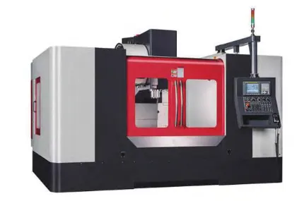
Sandvik Coromant tools were selected, including f 50mm indexable end mill inserts, Model: 490R-08T308M-MM/S30T; f 52mm indexable end mill inserts, Model: R300-1240E-PMS30T; f 80mm indexable end mill inserts, Model: R300-1240E-PMS30T.
During rough machining, the majority of the workpiece consists of rough surfaces, which further exacerbates tool wear. The cutting parameters of the tools during on-site testing are shown in Table 1.

During initial machining, the chips produced by the tool were curled and smooth.
After just 2 hours, the chips became elongated with wrinkled surfaces resembling squeezed shapes. Tool wear occurred suddenly; the tool was functioning normally one minute and could no longer be used the next, requiring a blade replacement.
To reduce costs and improve efficiency, the spindle speed, feed rate, and depth of cut were tested and adjusted.
Production efficiency improved to some extent, with the tool life extending from a maximum of 2 hours (while accounting for unforeseen tool wear) to a more stable 3 hours.
The scheduled tool changes after machining prevented production from coming to a standstill.
Further parameter adjustments were made, ultimately yielding optimized cutting parameters for the tool, as shown in Table 2.
The time between blade replacements can now be extended to 6–7 hours, significantly reducing tooling costs.

Finishing cutting parameters
Compared to the roughing stage, the finishing stage involves reduced machining allowances.
For tools of the same diameter, the spindle speed, feed rate, and back cutting depth are all increased, but they cannot be maintained at constant values like in roughing and have a certain range of variation, requiring continuous adjustment during machining.
During the finishing stage, tool selection for drilling and reaming must also be considered.
Due to unreasonable cutting parameters, these operations are more prone to hardening phenomena compared to milling, resulting in deformation of the machined hole diameter and part scrap.
The slot cavity width dimensions in finishing require high precision, so the impact of cutting parameters on dimensional accuracy must also be considered.
The DMU100P five-axis machining center is shown in Figure 7.
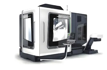
Taking a 50 mm indexable end mill as an example, Walter tools are selected, model WALTER 116166, with the following insert type: ADMT120430R-F56WSM35, for machining outer shapes, cavities, etc.
The cutting parameters for the f 50mm fly cutter section are shown in Table 3, and the tool cutting parameters for the finishing section are shown in Table 4.

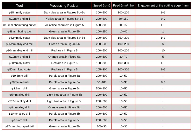
During the machining process, to overcome the lack of machining experience and the limitations of existing tools, the cutting parameters for roughing and finishing tools (spindle speed, feed
rate, and depth of cut) were continuously tested and optimized to determine reasonable cutting parameters.
Conclusion
Machining TC11 titanium alloy presents significant challenges due to its high hardness, poor machinability, and tendency to cause rapid tool wear and thermal damage.
Through in-depth analysis of the material’s properties, part structure, and machining requirements, this study successfully identified practical strategies to overcome these issues.
By selecting coated carbide tools with high wear resistance and thermal stability—especially those with PVD-applied TiAlN coatings—machining performance was significantly improved.
Circular inserts and high-cobalt drill bits were chosen for their enhanced heat dissipation and tool life, particularly under the demands of rough and finish machining.
Strategic use of layered milling, five-axis planar machining, and horizontal approaches for deep cavities helped minimize tool vibration, reduce cutting forces, and prevent chip accumulation.
These techniques ensured greater dimensional accuracy, smoother surface finishes, and extended tool service life.
Moreover, through iterative on-site testing and adjustment of cutting parameters, both roughing and finishing processes achieved optimized efficiency.
As a result, tool life was extended from 2 to over 6 hours, dramatically reducing tooling costs and production downtime.
This case study demonstrates that with proper tool selection, machining strategy, and parameter optimization, even difficult-to-machine materials like TC11 titanium alloy can be processed efficiently and cost-effectively.
FAQ
Why is machining titanium alloy materials like TC4 more difficult than steel?
Titanium alloys such as TC4 have low thermal conductivity and low specific heat, which lead to extremely high cutting temperatures during machining—often more than double that of 45 steel. This results in rapid tool wear, reduced tool life, and challenges in maintaining dimensional accuracy.
What are the key tool material requirements for titanium alloy machining?
Tool materials for titanium alloy machining must offer high thermal hardness, superior wear resistance, and oxidation resistance. Common choices include coated carbide tools, CBN (cubic boron nitride), PCD (polycrystalline diamond), and high-cobalt HSS grades to withstand extreme heat and friction.
How does the elasticity of titanium alloy affect surface finish during machining?
Titanium alloys have a low modulus of elasticity, causing the material to spring back after cutting, especially in thin-walled parts. This rebound leads to increased friction between the tool and the surface, resulting in poor surface finish and tool chipping.
What cutting parameters are recommended for turning titanium alloys like Ti-6Al-4V?
For turning TC4:
Roughing: V = 15–28 m/min, f = 0.25–0.35 mm/r, ap = 1–3 mm.
Finishing: V = 50–70 m/min, f = 0.1–0.2 mm/r, ap = 0.3–1 mm.
Low cutting speeds and increased depths of cut are recommended to manage heat buildup and tool wear.
Why is cutting speed more critical than depth of cut in titanium alloy machining?
Cutting speed has a significant effect on edge temperature, which accelerates tool wear and reduces tool life. In contrast, depth of cut has minimal influence on temperature. Therefore, low speeds and larger depths are optimal for roughing operations.
What is the role of cutting fluids in titanium machining, and which types are effective?
Cutting fluids help dissipate heat, flush away chips, and reduce cutting force. Effective options include water-based emulsions, synthetic oils, and halogenated lubricants. However, halogen coolants must be followed by pickling to remove salt crust and are not recommended during final part assembly.
How should tool geometry be optimized for titanium alloy machining?
Tool geometry should be designed for strength and chip control:
Roughing tools: Small front/back angles for rigidity.
Finishing tools: Larger rake and clearance angles for sharpness and surface quality.
Drills: 135°–140° point angle, polished flutes, and 25°–30° helix angle.
Milling cutters: 6°–12° back angle, 35°–40° helix angle.
What are the challenges and best practices in titanium alloy tapping?
Titanium's low elasticity and high friction cause the tap to chip or seize. Use taps with fewer teeth, larger cutting cone angles, negative rake relief, and shorter lengths for rigidity. Machine tapping is preferred to avoid manual feed inconsistencies.
How is residual stress managed in titanium alloy parts after machining?
Titanium alloy components develop residual stresses due to heat and mechanical forces. To relieve these, parts should be annealed in a vacuum furnace at 600°C–650°C, followed by air cooling. This process ensures stress relief while avoiding hydrogen embrittlement.
What are the current advancements in titanium alloy milling technology?
Advanced techniques such as insert milling and high-speed carbide tools (e.g., Jabro, YG10H) have improved roughing efficiency by 3–4 times. The use of coated tools, optimized cutter geometry, and cutting path strategies like climb milling have significantly enhanced tool life and surface finish.
How do PVD and CVD coating methods differ in tool manufacturing?
PVD (Physical Vapor Deposition) allows for precise, low-temperature coating application—ideal for maintaining tool integrity—while CVD (Chemical Vapor Deposition) offers thicker coatings with strong adhesion, suited for heavy-duty applications.
What results were achieved through optimized tool and parameter selection for TC11 alloy?
By selecting circular inserts, high-cobalt drills, TiAlN-coated tools, and optimizing cutting parameters, machining efficiency improved dramatically. Tool life more than tripled, surface quality improved, and production costs were significantly reduced.

