Large diameter machining refers to the precision cutting, turning, and milling of oversized cylindrical or disc-shaped components, often exceeding one meter in diameter.
Industries such as aerospace, energy, heavy equipment, shipbuilding, and oil & gas widely use these parts for components like turbines, pressure vessels, windmill hubs, and large bearings that demand high accuracy and structural integrity.
Despite its importance, manufacturers consider big diameter machining one of the most challenging areas in modern manufacturing.
The sheer size and weight of the workpieces introduce difficulties in material handling, fixturing, and balancing during rotation.
Machine tools must withstand high loads while maintaining tight tolerances across large surface areas. Moreover, thermal expansion, vibration, tool deflection, and long cycle times significantly increase the risk of dimensional errors and surface defects.
These factors make achieving both precision and efficiency in big diameter machining far more complex than in small or medium-sized work.
Case Study
The following case study illustrates this point: A large-diameter, thin-walled aluminum alloy sealing cap part is made of 2A12-T4 (GB/T 3880.1—2006) aluminum alloy.
This material exhibits the following machining characteristics:
① Low hardness and high plasticity, prone to tool sticking during cutting.
② High thermal expansion coefficient, sensitive to temperature changes.
③ Low elastic modulus, prone to deformation under clamping forces.
The structural dimensions of the large-diameter aluminum alloy sealing cap part are shown in Figure 1.
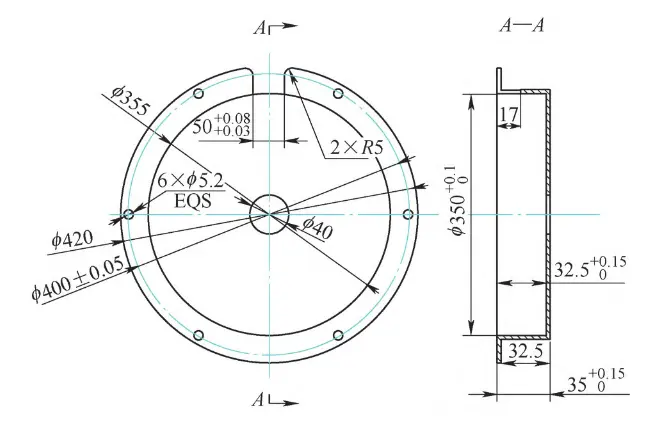
The workpiece has a total length of 35 mm, a step depth of 32.5 mm, a maximum outer diameter of 420 0
-0.32 mm, an outer diameter of 355 mm at the step, an inner diameter of 350 +0.1
0 mm, and a wall thickness of 2.5 mm.
Six φ5.2 mm locating holes are uniformly distributed around the φ400±0.05 mm circumference of the step end face.
A single through slot with a width of 50+0.08
+0.03 mm and depth of 17 mm is milled at the large outer diameter.
The challenge lies in minimizing deformation during positioning hole and slot machining to ensure hole tolerance for the thin-walled workpiece.
With a wall thickness of 2.5 mm, the seal cover part faces significant machining challenges when using traditional turning and milling processes.
Factors such as cutting forces, clamping forces, and internal stresses readily cause deformation.
Issues with Traditional Machining Processes
The conventional process route employs precision turning of the inner bore followed by double-top turning of the outer contour.
A 40mm-thick sheet of 2A12-T4 aluminum alloy was selected for blanking. To prevent significant deformation of the raw blank, waterjet cutting equipment was used, leaving a 5mm machining allowance on the outer diameter.
Rough turning was performed first using a self-centering chuck with reverse jaws. The workpiece end face was turned to a smooth finish, with the outer diameter left with a 2–3 mm allowance relative to the finished dimension.
After turning the workpiece, it was re-clamped with the outer diameter aligned to the diameter of the previously machined allowance.
The entire end face was turned, leaving a 1 mm allowance relative to the finished workpiece dimension.
Drill the hole using a φ38mm drill bit. Turn the φ40mm bore to final dimensions.
> Finish Turning and Mandrel Setup
Machine φ350 +0.1
0 mm with a 2mm allowance, to a depth of 35mm. Allow for 72 hours of natural aging.
Clamp using a self-centering chuck. Finish-turn the end face, controlling the overall length of the workpiece.
Finish-turn φ350 +0.1
0 mm to final dimensions. Mount the workpiece on a stepped mandrel with outer diameters of φ420 mm and φ350 0
-0.1 mm, depth 32.5 mm.
Secure the workpiece using a φ150 mm nylon center fitted to the diameter and 60° taper of the live center mandrel.
Finish-turn the outer diameters φ420 0
-0.32 mm and φ355 mm while controlling the depth dimension.
Using a clamping plate to secure the mandrel and workpiece on the machining center table, machine six φ5.2 mm locating holes and mill a 50 mm wide, 17 mm deep through slot.
> Key Technical Challenges and Process Improvement
Despite mandrel support, the inner bore of the thin-walled aluminum alloy seal cover part is prone to bulging at the φ350 mm bottom face and dimensional distortion during milling due to cutting and clamping forces.
This causes localized oversize in the φ350 +0.1
0 mm and 32.5 +0.15
0 mm, and 35 +0.15
0 mm.
This machining process presents three major technical challenges:
① Radial deformation occurs easily in thin-walled structures under clamping forces.
② Milling slots and drilling holes readily induce vibration, leading to dimensional deviations.
③ High surface quality requirements mandate a surface roughness value of Ra ≤ 1.6 μm.
To address these issues, a process improvement was implemented. A technical approach was adopted: “special fixture design → process route optimization → process control” to systematically resolve the aforementioned problems.
Improved Machining Process
Machining Strategy
To address the challenges of deformation, high internal stress, and difficult precision control during turning of sealing cap components, process innovation and fixture optimization were implemented to reduce the impact of clamping force, cutting force, cutting heat, and internal stress on the workpiece.
Key research focuses on specialized fixture design and cutting parameter optimization, developing dedicated tooling for ultra-thin-walled aluminum alloys.
This suppresses vibration deformation and thermal expansion during cutting, achieving high-precision process solutions with minimal errors in seal surface roundness and flatness.
Through the synergy of specialized clamping fixtures and new processes, this approach resolves issues such as hole deformation and surface irregularities caused by wall thinning and insufficient rigidity in traditional machining. This enhances the airtightness and durability of the sealing cover.
This process effectively reduces scrap rates, shortens processing cycles, and overcomes technical bottlenecks in the efficient, precision machining of ultra-thin-walled aluminum alloy seals, enabling the production of batches of qualified products.
Process Flow
Improved processing flow for seal cover components: Blanking → Rough turning of small hole ID, OD, and end face → Finish turning of small hole ID, semi-finish turning of OD → Drilling of process thread holes → Finish turning of ID (φ350 +0.1
0 mm, φ32.5 +0.15
0 mm) and end face, setting full length → Finish turning of OD → Milling of slots, drilling → Deburring → Surface treatment → Inspection.
Detailed content follows.
(1) Blank Cutting
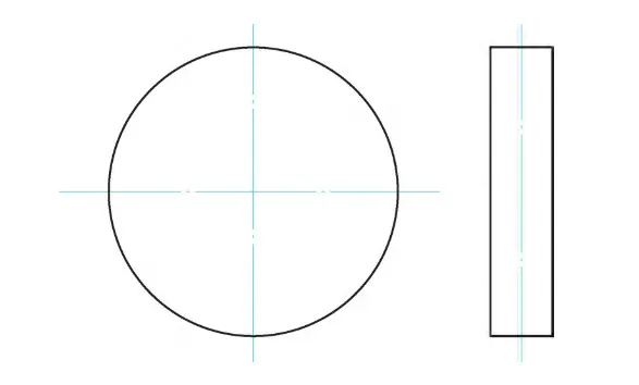
Blank cutting is shown in Figure 2. A 40mm-thick sheet of 2A12-T4 aluminum alloy is selected. To prevent significant deformation of the blank, waterjet cutting is employed, leaving a 5mm machining allowance on the outer diameter.
(2) Rough Turning of Small Hole ID, OD, and End Face
Clamp the workpiece in a self-centering chuck, support the opposite end with a tapered center, and use a U-drill or twist drill to machine the φ37mm hole.
Rough-turn the outer diameter with a 2mm allowance. After turning the end face until it is visible, reposition and clamp the workpiece.
Align the outer circle with the machined dimension, leaving a 2mm allowance along the entire length.
(3) Finish turning small hole, semi-finish turning outer diameter
Finish turn the small inner hole to φ40 +0.05+0 mm. Mount the workpiece on a mandrel, using the inner hole as the reference, and machine the outer diameter to φ421 mm.
(4) Drilling Process Thread Holes at One End of the Workpiece
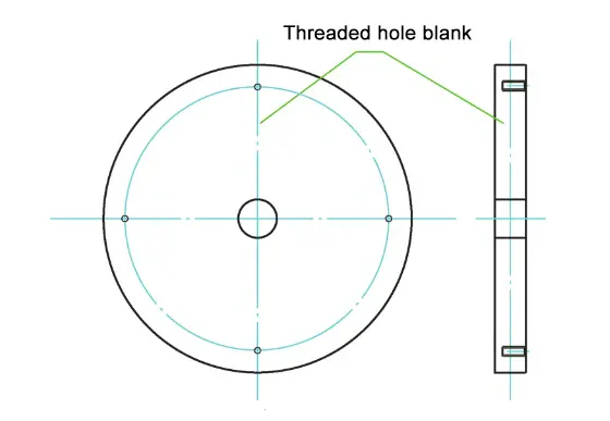
Using a T-V1165M vertical machining center, machine four evenly distributed M12 process thread holes with a depth of 10mm on the circumference of φ (400±0.05)mm. Figure 3 shows the thread hole structure.
(5) Finish turning the inner diameter and end face, controlling the overall length of the workpiece
Using a CSK6163 CNC lathe, machine the inner diameters φ350 +0.1+0 mm and φ32.5 +0.15+0 mm. Employ a specialized fixture to axially clamp the workpiece with four M12 screws, preventing deformation caused by radial clamping.
The operator controlled the clearance between the fixture’s shoulder and the workpiece’s small inner diameter hole within 0.05–0.07 mm.
The fixture consists of a body and screws. The fixture achieves axial clamping by tightening screws through the workpiece’s process threaded holes, which operators can remove after machining.
Fixture Design
Engineers designed a dedicated fixture for precision turning of the inner diameter and end face, as well as for setting the full length. Figure 4 shows how the fixture clamps the workpiece.
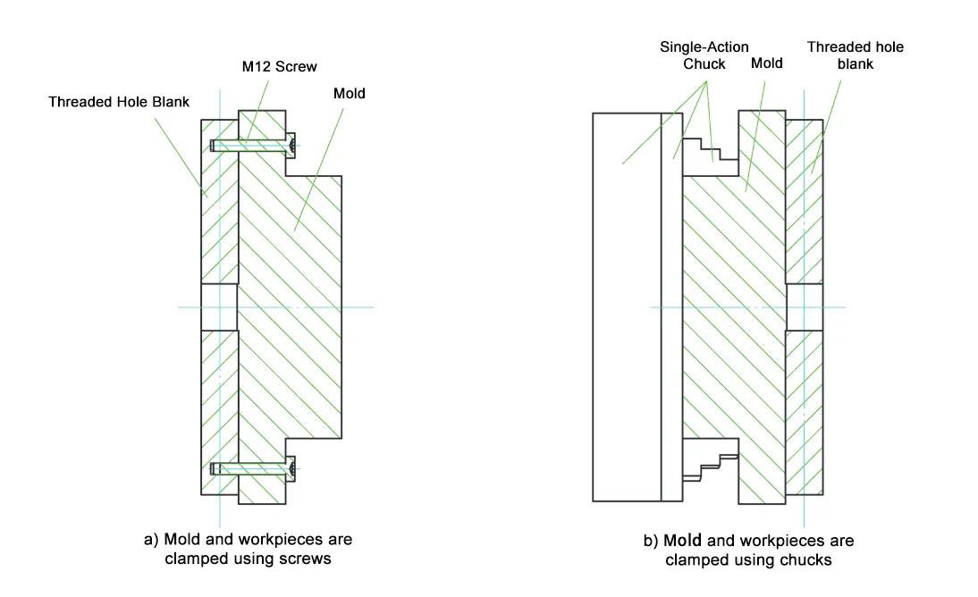
As shown in Figure 5, four equally spaced through holes (φ12.15 mm) are machined around the circumference of the fixture (φ400±0.05 mm).
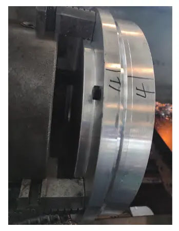
The fixture is clamped using a single-action chuck, with the locating end face and locating shoulder outer diameter aligned and positioned.
Machine threaded holes identical to those on the threaded-hole blank. Secure the threaded-hole blank to the fixture with four M12 screws for a tight fit.
Advantages of this specialized fixture: The flange on the fixture in Figure 4 provides locating support.
The clearance between the flange and the small inner hole of the threaded blank is 0.05–0.07 mm.
The clamping method using four M12 screws applies axial force to the threaded blank, preventing radial clamping deformation of the inner hole end face during machining of the large-diameter, thin-walled aluminum alloy sealing cap.
> Modular Specialized Fixture for Outer Diameter Turning
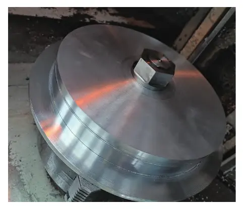
For the finish turning of the outer diameter, engineers designed a modular specialized fixture (see Figures 6 and 7) consisting of a single-jaw chuck, main body, locating rod, pressure cap, and nut.
They secure the main body and locating rod with a threaded connection.
The operator clamps the semi-finished workpiece tightly against the main body using the pressure cap and nut, engaging the locating rod threads to ensure the workpiece surface stays in close contact with the main body surface.
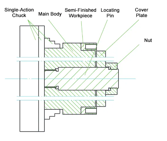
Advantages of this modular specialized fixture: The clearance between the main body’s outer diameter and the semi-finished workpiece’s inner bore is controlled between 0.07 and 0.14 mm.
The depth of the semi-finished workpiece’s inner bore matches the positioning step depth of the main body, with tolerances maintained within ±0.02 mm.
This provides full support, preventing clamping deformation during machining of the sealing cap component.
Mount the cover on the locating rod and secure the workpiece with a nut. Clamp the center drill in a drill chuck on the locating rod to machine the center hole, supported by a live center.
During turning of the semi-finished workpiece, the axial pressure generated by the cutting edge ensures the inner bore end face tightly contacts the support surface of the main body (as shown in Figure 7), preventing vibration and deformation caused by insufficient workpiece rigidity.
Cutting Parameter Optimization
After optimizing cutting parameters, the following values were determined for finish turning: cutting speed 120–180 m/min, feed rate 0.10–0.15 mm/r, and depth of cut 0.3–0.5 mm. Ensure adequate cooling with a cutting fluid flow rate ≥15 L/min.
The finishing process employed carbide tools for Sunde aluminum alloy, achieving breakthroughs in milling slots and drilling with high-quality standards: roundness error ≤0.05 mm and surface roughness Ra=1.6 μm.
> Design and Function of the Dedicated Fixture
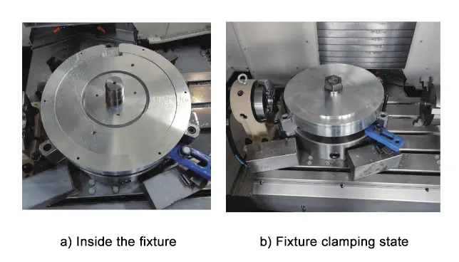
For milling slots and drilling operations, a dedicated fixture was designed (see Figure 8). The lower section of this fixture comprises a main body, a pressure cap, and a nut.
The operator clamps the main body onto a self-centering chuck mounted on a fixed workbench.
After precisely turning the inner bore and outer diameter of the seal cover, the operator inserts it into the main body.
Then, the operator places the pressure cap inside the turned workpiece and tightens the nut to press the pressure cap and workpiece securely against the main body.
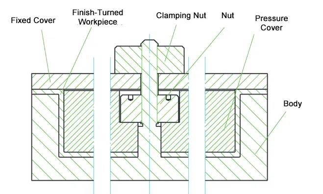
The outer diameter of the precision-turned workpiece should have a clearance fit of 0.07–0.14 mm with the body’s inner bore.
The depth of the workpiece’s outer diameter should align as closely as possible with the locating step depth of the body, with tolerances controlled within ±0.02 mm.
This ensures full support, preventing clamping deformation during machining of the sealing cap component.
A clamping nut ensures tight contact between the upper fixed cover, the finished workpiece, and the body.
This enhances workpiece rigidity while preventing deformation caused by cutting forces.
> Machining Results and Quality Improvement
Figure 9 shows the actual milling groove and drilling fixture.
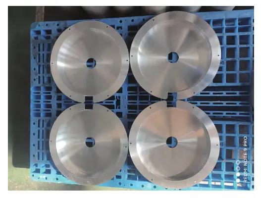
Actual machining demonstrates that the optimized process controls groove width tolerance within ±0.05 mm and hole spacing error within ±0.05 mm, increasing the pass rate from 70% to 99%. Figure 10 shows the finished thin-walled aluminum alloy sealing cap.
Conclusion
This paper analyzes the causes of machining deformation in large-diameter thin-walled aluminum alloy sealing caps.
We improved the original clamping method and machining approach by adopting a combined axial support and clamping technique.
This improvement increases workpiece rigidity and minimizes deformation caused by clamping forces. As a result, we successfully keep deformation within tolerance limits.
This innovative process effectively resolves machining challenges for sealing cap components and holds significant potential for broader application.
FAQ
What is large-diameter machining and why is it important in modern manufacturing?
Large-diameter machining refers to precision turning, milling, and cutting of oversized cylindrical or disc-shaped components—often exceeding one meter in diameter—used in aerospace, energy, shipbuilding, and heavy equipment. Its importance lies in maintaining structural integrity and tight tolerances for mission-critical parts like turbines, windmill hubs, and pressure vessels.
What are the key challenges in machining thin-walled aluminum alloy components?
Challenges include radial deformation under clamping forces, vibration during slot milling and drilling, thermal expansion affecting dimensional accuracy, and difficulty achieving high surface quality requirements (Ra ≤ 1.6 μm). These issues can result in oversize holes, uneven wall thickness, and poor pass rates.
How do cutting forces and clamping forces affect thin-walled part accuracy?
Cutting and clamping forces induce elastic deformation in thin-walled structures, leading to dimensional distortion such as bulging of the bore or oversizing of critical diameters. Proper fixture design and process control are essential to balance forces and keep deformation within tolerance limits.
Why is fixture design critical in large-diameter machining?
A well-designed fixture provides full support, distributes clamping forces axially instead of radially, and minimizes vibration during machining. This prevents part deflection and ensures accurate tolerances on inner diameters, outer diameters, and step depths.
How can modular specialized fixtures improve machining results?
Modular fixtures allow precise positioning, controlled clearance fits (0.07–0.14 mm), and adjustable axial clamping. This design reduces radial stress, improves rigidity, and enables repeatable, high-accuracy machining for batch production.
What cutting parameters are recommended for finish turning large-diameter aluminum parts?
Optimized cutting parameters include a cutting speed of 120–180 m/min, feed rate of 0.10–0.15 mm/r, depth of cut of 0.3–0.5 mm, and a cutting fluid flow rate ≥15 L/min. These parameters ensure smooth cutting, reduce tool wear, and help maintain surface roughness Ra ≤ 1.6 μm.
