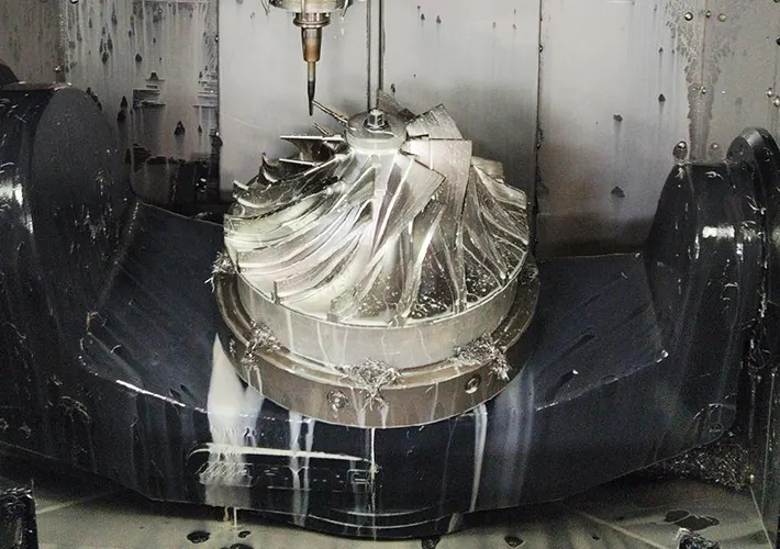
The current UAV technology is developing rapidly, and there is a growing demand for the manufacturing of its core components such as thin-walled impellers.
Five-axis CNC machining has become the preferred technology for manufacturing thin-walled impellers and other complex curved components due to its superior flexibility and machining accuracy.
It effectively addresses the limitations of conventional machining methods in terms of both precision and efficiency.
Compared with conventional machining technologies, five-axis CNC machining can significantly shorten processing time and reduce production costs while maintaining the accuracy and quality of thin-walled impeller parts.
This advantage ultimately enhances the competitiveness of manufacturers in the market. It is of great significance to explore the application of five-axis CNC machining technology in the processing of thin-walled impellers for UAVs.
Five-axis CNC machining technology points
Planning tool path
The rationality of the tool path will not only affect the smoothness of the machining process, but also affect the quality and performance of the product.
In practice, computer-aided manufacturing (CAM) software can be utilized to plan precise toolpaths for complex surfaces, minimizing unnecessary cutting and reducing processing time.
At the same time, it ensures that the surface finish consistently meets the required quality standards.
Specific operation should pay attention to the following two points.
(1) Optimizing the tool path requires the use of deep learning algorithms and big data analysis methods.
A standard prediction model is established by deeply analyzing historical machining data to determine the machining path corresponding to different machining parameters.
For example, an adaptive path optimization system based on machine learning can monitor the real-time condition of the workpiece and automatically adjust cutting parameters.
This proactive adjustment helps prevent machining errors caused by minor workpiece deformations, thereby ensuring consistent machining accuracy.
(2) Planning the tool path needs to take into account the cost of tool wear, set the machining sequence scientifically, and reduce the number and time of unplanned downtime.
Practice shows that the optimization of tool use strategy can reduce tool costs, significantly improve machining efficiency, to achieve the scientific allocation of resources and make full use of the lean production goals have an important role to achieve.
Real-time monitoring and adjustment
Real-time monitoring is a key aspect of five-axis CNC machining, which needs to rely on a variety of sensors and intelligent algorithms.
For example, based on displacement sensors, force sensors, real-time capture of cutting force, temperature and vibration changes, and upload the collected data to the central control system.
The probability of problems in the machining process is predicted through the analysis model, and the parameters are adjusted in time to reduce the possibility of problems.
For example, in thin-walled impeller machining, the introduction of real-time monitoring mechanism can significantly improve the product qualification rate.
This is because the mechanism has an adaptive function that can immediately adjust the machining parameters, such as cutting speed, feed or coolant flow, when abnormal signals are detected, reducing the impact of material deformation and tool wear.
This intelligent adjustment not only improves machining quality and extends tool life, but also reduces production costs, prompting the manufacturing industry to develop in the direction of intelligence.
CNC Programming
CAM software as a pre-design and mid-processing connection bridge, can significantly shorten the programming time, improve processing efficiency.
CAM software used in thin-walled impeller processing, not only can automatically optimize the tool path, but also reduce manual intervention to ensure the machining accuracy of complex geometric shapes.
The built-in analysis model plays an important role in predicting and avoiding the risk of collision to ensure the reliability and safety of machining.
In addition, the advantages of CAM software extend to the systematic analysis of material properties.
By accessing comprehensive material cutting performance databases, the software can recommend cutting parameter combinations tailored to the specific machining conditions, ensuring that both processing quality and efficiency meet or exceed expectations.
For modern manufacturing industry, the role of CAM software is mainly through the simulation of the real processing environment, identify in advance, timely correction of error sources, to ensure the dimensional accuracy of thin-walled impeller, surface quality.
In summary, CAM software-based programming for five-axis CNC machining delivers consistent performance by accelerating the transition from design to manufacturing.
Through scientific toolpath planning and optimized parameter selection, it ensures machining accuracy and efficiency, ultimately driving advancement in the unmanned aerial vehicle (UAV) industry.
Three-dimensional simulation and error compensation technology
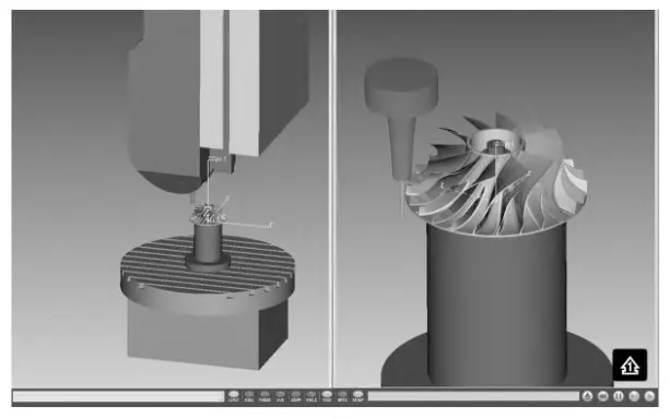
Three-dimensional simulation technology helps technicians to preview the entire machining process in a virtual environment, and identify and deal with potential technical problems.
For example, finite element analysis (FEA) can simulate the interaction between the cutting tool and the workpiece, predicting cutting force distribution, thermal deformation, and dynamic response.
This predictive capability helps control vibration and deformation levels, thereby safeguarding the geometric accuracy and surface quality of thin-walled impellers.
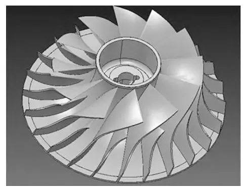
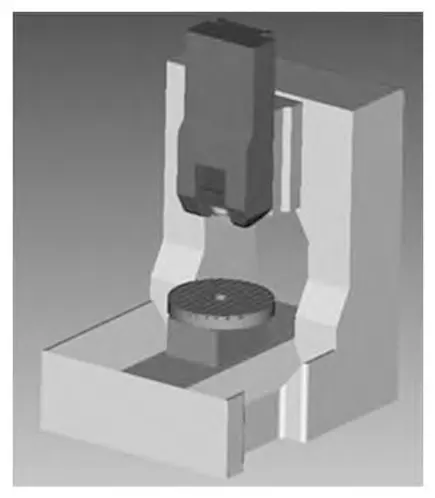
In practice, emphasis should be placed on error compensation technology through comprehensive analysis of potential error sources within the machining process.
Establishing corresponding standard models enables the quantification of these errors, providing a solid foundation for developing effective compensation strategies.
By monitoring machine temperature changes in real time and adjusting processing parameters accordingly, it is possible to effectively mitigate machining errors caused by thermal deformation.
Additionally, by analyzing historical machining data using machine learning algorithms, the error compensation program can be adjusted in a targeted and intelligent manner, further enhancing dimensional accuracy and process stability.
The integration of three-dimensional simulation with error compensation strategies offers significant advantages in precision manufacturing.
This combination not only enhances processing efficiency and reduces the cost associated with trial-and-error adjustments, but also improves the overall reliability of the machining process.
Furthermore, by optimizing error compensation methods, manufacturers can effectively enhance product performance and strengthen market competitiveness.
The simulation results are shown in Figure 3.
Optimization measures of five-axis high-efficiency CNC machining technology for drone thin-walled impeller
Scientific selection of materials
As one of the core parts of the UAV power system, the thin-walled impeller has very strict requirements on the performance of processing materials.
Using high-strength and lightweight materials to process and manufacture thin-walled impellers can make the UAV performance reach the ideal level through technological innovation.
Among the existing materials, carbon fiber-reinforced polymer (CFRP) (Fig. 4) and titanium alloy are used more frequently.
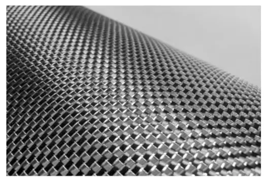
On the one hand, CFRP has an outstanding strength-to-weight ratio, and impellers made of CFRP are able to reduce their weight to about 70% of that of aluminum alloy impellers while maintaining good mechanical properties.
The use of this material can significantly reduce the weight of the UAV, improving its range and flight stability.
Advantages of CFRP and Titanium Alloy in Impeller Manufacturing
On the other hand, although titanium alloys are more expensive to purchase, they have high strength and corrosion resistance, making them suitable for extreme environments.
Applying titanium alloy to impeller manufacturing can extend the mean time between failures and prolong the service life of the UAV while ensuring its performance.
Microstructure Control and Future Prospects for Material Innovation
From the perspective of materials science, the macroscopic properties of materials mainly depend on the microstructure. The microstructure of the material, such as the size and distribution, can be controlled to further improve the performance of thin-walled impellers.
For example, when processing magnesium alloy impellers based on powder metallurgy technology, the strength and toughness of the impeller can be significantly improved through grain refinement.
Applying this impeller to the power system can improve the flight speed and increase the endurance of the UAV.
In conclusion, the application of high-strength and lightweight materials to the processing of thin-walled impellers can promote the improvement of UAV performance.
In the future, by further exploring new materials and processes, the adaptability of UAVs to the operating environment can be further enhanced and their application prospects can be expanded.
Reasonable setting parameters
The rationality of cutting parameters directly affects the accuracy and efficiency of processing, and plays a decisive role in the surface quality of the thin-walled impeller and the integrity of the internal microstructure.
Due to the thin-walled structure of the impeller and its tendency to deform under cutting forces, it is generally recommended to prioritize the use of small-diameter tools for layered machining.
To effectively control cutting forces and minimize deformation, the cutting depth for each layer should not exceed 0.5 mm.
This approach helps maintain the geometric integrity and dimensional accuracy of the impeller throughout the machining process.
Real-Time Monitoring and Dynamic Adjustment of Cutting Parameters
In practical applications, cutting force and temperature should be monitored in real time.
Based on the real-time monitoring data, cutting parameters should be dynamically adjusted to ensure machining accuracy and surface quality, especially for complex curved surfaces.
Through intelligent control, the process can consistently achieve the desired precision
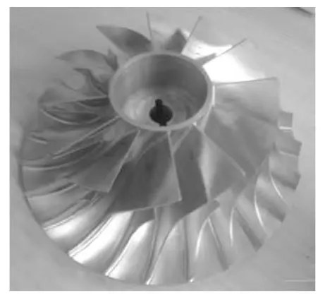
The finished impeller is shown in Figure 5.
Intelligent Parameter Generation and Fault-Tolerant Mechanisms
Cutting parameter setting is the key to 5-axis CNC machining, and its rationality is closely related to the performance of thin-walled impeller.
Therefore, engineers must pay careful attention to both preliminary planning and dynamic adjustment throughout the machining process.
Engineers must ensure that cutting parameters are properly set to match the specific machining requirements.
Failure to do so may result in compromised machining quality and reduced operational efficiency due to inappropriate parameter settings.
If conditions permit, engineers can introduce intelligent algorithms into the machining workflow.
These algorithms can automatically generate cutting parameter programs based on the physical properties of the workpiece material, tool material, and the degree of tool wear.
Technicians can then evaluate and select from these suggested programs according to the actual machining conditions.
This approach ensures the rationality of cutting parameters while minimizing the risk of human error.
In addition, due to the complexity of thin-walled impeller machining, the cutting parameters must adhere to strict specifications. Engineers should introduce a fault-tolerant mechanism to address this challenge.
Intelligent algorithms automatically identify parameter anomalies and respond by adjusting them back to the normal range or switching to an alternate machining program.
This helps minimize the impact of parameter deviations on the machining process and ensures consistent product quality.
Table 1 shows the standard cutting parameters.

Implementation of quality control testing
In the era of Industry 4.0, the degree of intelligence and automation of the manufacturing industry has increased significantly, and the importance of the online inspection system, as a core component of intelligent manufacturing, has become increasingly important.
The online inspection system can monitor dimensional accuracy, surface roughness, microstructure changes, and other parameters in real time.
Based on the analysis results, it can dynamically adjust processing parameters during machining. This proactive approach helps avoid the risk of increased scrap rates caused by relying solely on post-process inspection..
Applying this system to thin-walled impeller processing can not only improve the yield rate, but also significantly reduce the error of manual inspection and reduce costs.
Practice shows that integrating the machine vision-based online inspection system into a five-axis CNC machining line can ensure the accuracy of thin-walled impellers by automatically identifying and correcting deviations.
In addition, combining the system with a data analysis platform can predict potential failures and ensure the continuity and efficiency of the machining process by maintaining the machining equipment in advance. The five-axis machining center is shown in Figure 6.
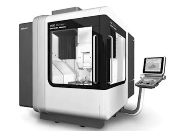
Integrating a five-axis machining center with an online inspection system is not a simple stack of hardware, but rather a complete machining system constructed by seamlessly interfacing management software, CNC machine tools and control systems.
In order to achieve this goal, manufacturers must possess not only a solid hardware foundation, a robust software infrastructure, and strong data analysis capabilities.
They must also deepen system integration and enhance the level of intelligence in manufacturing processes. These efforts collectively support the sustainable development of the unmanned aerial vehicle (UAV) industry.
Conclusion
Five-axis CNC machining technology has significant advantages in the processing of thin-walled impellers of UAVs.
By planning the tool path, real-time monitoring and adjustment, CNC programming and three-dimensional simulation, it can significantly improve the processing accuracy and efficiency, and effectively control the production cost of thin-walled impeller.
Optimizing material selection, parameter setting, and quality control testing has improved the adaptability, flexibility, stability, and reliability of 5-axis CNC machining technology.
These enhancements specifically benefit the processing of thin-walled impellers used in unmanned aerial vehicles. As a result, the technology can meet the machining requirements of different materials and significantly improve product precision.
In the future, manufacturers should continuously optimize five-axis CNC machining solutions to promote the development of the UAV manufacturing industry.
FAQ
What are the advantages of using five-axis CNC machining for UAV thin-walled impellers?
Five-axis CNC machining offers superior flexibility and precision, making it ideal for manufacturing complex UAV components like thin-walled impellers. It reduces production time, enhances surface quality, and lowers overall costs compared to conventional methods.
How does CAM software enhance five-axis CNC machining of thin-walled impellers?
CAM software optimizes toolpaths, minimizes manual intervention, and simulates the entire machining process to prevent collisions. It ensures machining accuracy, especially for complex geometries in UAV thin-walled impellers.
Why is toolpath optimization important in five-axis CNC machining of UAV impellers?
Optimizing toolpaths using machine learning and big data enhances machining efficiency, reduces tool wear, and ensures consistent quality. It allows for real-time adjustments based on workpiece behavior, improving the precision of UAV impeller manufacturing.
What role does real-time monitoring play in five-axis CNC machining of thin-walled impellers?
Real-time monitoring with force, vibration, and temperature sensors enables adaptive control of cutting parameters. This minimizes deformation and tool wear, improving the yield rate and machining accuracy of UAV thin-walled impellers.
Which materials do manufacturers commonly use for UAV thin-walled impellers?
CFRP and titanium alloys are widely used for their excellent strength-to-weight ratios and resistance to harsh environments. These materials reduce UAV weight, enhance performance, and extend service life.
How does three-dimensional simulation support five-axis CNC machining of UAV impellers?
Three-dimensional simulation and finite element analysis predict machining challenges like thermal deformation and vibration. When combined with error compensation techniques, they ensure dimensional accuracy and reduce reliance on trial-and-error adjustments.
How should cutting parameters be set for machining UAV thin-walled impellers?
For thin-walled UAV impellers, a layered cutting depth under 0.5 mm using small-diameter tools is recommended. Intelligent systems can dynamically adjust parameters based on sensor feedback, ensuring dimensional stability and surface quality.
How does online inspection improve the quality control of UAV thin-walled impellers?
Online inspection systems using machine vision and sensors can detect deviations during machining, reducing the risk of defects and rework. These systems improve precision, lower costs, and support the smart manufacturing of UAV impellers.
What future trends are shaping the five-axis CNC machining of UAV components?
Future trends include the use of powder metallurgy for grain refinement and material innovation to improve strength and fatigue resistance. These advancements will further enhance UAV performance, endurance, and adaptability.
How does integrating five-axis CNC machining with intelligent systems benefit UAV manufacturing?
Integrating five-axis CNC centers with software, inspection systems, and data platforms creates an intelligent manufacturing ecosystem. This improves reliability, reduces manual errors, and enhances the overall competitiveness of UAV manufacturers.

