Angular geometric tolerance, a type of geometric dimensioning and tolerancing (GD&T) specification, controls how precisely manufacturers must hold one feature’s orientation (its slope or inclination) relative to another feature or reference (datum).
In simple terms, it sets the allowable deviation of an angle from its intended value. Instead of just specifying “this surface should be at 45°,” designers define a tolerance zone.
This zone is often bounded by two imaginary planes, within which the feature’s surface or axis must remain. Common GD&T symbols for angular orientation control include:
- Angularity (∠) — Controls the angle between a feature and a datum.
- Perpendicularity (⊥) — Special case: 90° angular tolerance.
- Parallelism (∥) — Special case: 0° angular tolerance.
Why it’s difficult to ensure angular geometric tolerances on complex planes?
Ensuring tight angular tolerances on complex surfaces or planes is challenging because:
Complex surface geometry makes reference alignment tricky
- Inspectors measure angular tolerances relative to a datum.
- On irregular or multi-faceted surfaces, establishing an accurate, stable datum plane is difficult, which affects measurement accuracy.
Multiple inclination changes
- A complex plane may have curvature, compound angles, or intersecting features.
- Even a small error in one section can throw off the entire angle measurement.
Accumulation of machining and setup errors
- Fixtures must hold the part at a precise orientation during machining.
- In complex geometries, each extra setup can add angular deviations.
Measurement limitations
- CMM (Coordinate Measuring Machine) probes and optical scanners must interpret many points to define the actual plane.
- If the surface contains interruptions like holes, steps, or irregular edges, the “best-fit” angle shifts depending on which points inspectors select.
Tool access and deflection
- On complex planes, cutting tools often work at awkward orientations.
- Tool deflection, chatter, and uneven cutting forces can cause angular errors.
Machining Case Show
Designers of piston rod components for the main shock absorption function of aircraft landing gear increasingly use an integrated design method.
This method combines the wheel shaft and the piston rod body.
Manufacturers are increasing both the number and the requirements for stop keys on the wheel shaft of these components.
These requirements include geometric tolerance, width dimensional tolerance, and angular tolerance between the keys.
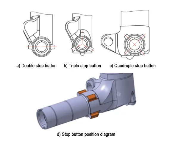
Typically, such components only have two keys. In recent years, piston rods often feature three to four keys (see Figure 1). The manufacturing quality is difficult to ensure due to the influence of the component’s overall structure..
With four stop keys evenly distributed around the circumference and inconsistent key thickness dimensions, the manufacturing difficulty is extremely high.
As the demand for large aircraft continues to grow, future designs may incorporate more stop keys on the wheel hub. The number of stop keys may increase compared to current designs
When machining this type of part, engineers ensure that the tolerance dimensions of the four stop keys meet requirements.
They also ensure that the angular relationship between the keys meets requirements. Additionally, they ensure that the symmetry of the key mating surfaces relative to the wheel axle meets requirements.
They develop a stable and effective machining method and tooling system to guarantee machining quality. This approach also improves production efficiency.
Technical Requirements for Piston Rod Stop Keys
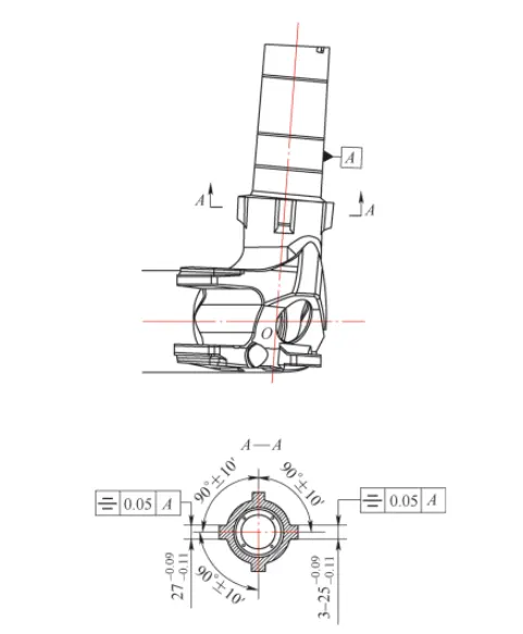
Figure 2 illustrates the technical requirements for stop keys. The four stop keys serve as the critical structural features for the wheel shaft to engage with the aircraft wheel.
Designers specify dimensional tolerances for the mating dimensions as tight as 0.02 mm. They require the wheel shaft’s symmetry to be within 0.05 mm and set the angular distribution tolerance at ±10′.
The machining process requires multiple workstations to complete the processing of all stop keys.
Processing Process and Dimension Calculation Principles
Processing Process Using a Five-Axis Machining Center
Machinists primarily select a five-axis machining center for the final machining of this type of stop key after heat treatment.
They may also choose a four-axis horizontal CNC boring machine center for the same purpose.
When using a five-axis machining center, the equipment offers unique processing advantages.
As a result, there are virtually no requirements for the part’s clamping posture during processing. There are also virtually no requirements for workstation changes during processing.
Simply adjust the shaft with the stop key to the plane containing the machine tool’s spindle axis.
Then use spindle rotation to achieve coordinate transformation. This completes the processing.
Processing Process Using a Four-Axis Horizontal CNC Boring Machine
(1) Stop key machining process for this type of part
The machining process is as follows:
Material procurement → Turning (machining the part’s reference outer diameter) → CNC milling (rough machining the outer contours of the four stop keys) → CNC milling (finishing the outer contours of the four stop keys, with a 1mm finishing allowance reserved for the mating surface) → Heat treatment (to alter the material properties of the part and meet the technical requirements of the design drawings) → Turning (re-finish the locating reference outer diameter of the part to eliminate errors caused by heat treatment deformation) → CNC boring (finish the four stop keys; this is a critical process and the most important step in meeting the technical requirements for the stop keys) → Inspection (comprehensive inspection of the dimensions and geometric tolerances of the stop keys) → Protective storage.

(2) Processing process of the CNC boring operation after heat treatment
Details as follows.
» Part clamping and alignment.
Operators use the A-axis on a four-axis machining center together with a center frame positioned at the same height as its center.
Operators clamp and align the part in a “one clamp, one hold” configuration. They keep the radial runout of both end reference outer diameters within ≤0.03 mm.
At the same time, they align the axis of the outer diameter where the stop key is located with the locating outer diameter axis of the part on the same horizontal plane.
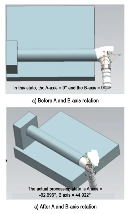
At this point, the axis settings are A-axis = 0° and B-axis = 0°. Figure 3 illustrates how operators clamp and rotate the part.
» Actual machining steps for the stop key.
After operators clamp and align the part, they rotate the machined surface of the stop key to a position perpendicular to the machine tool spindle to machine the stop key.
This process requires the machine tool to perform composite rotation of the A-axis and B-axis (work table).
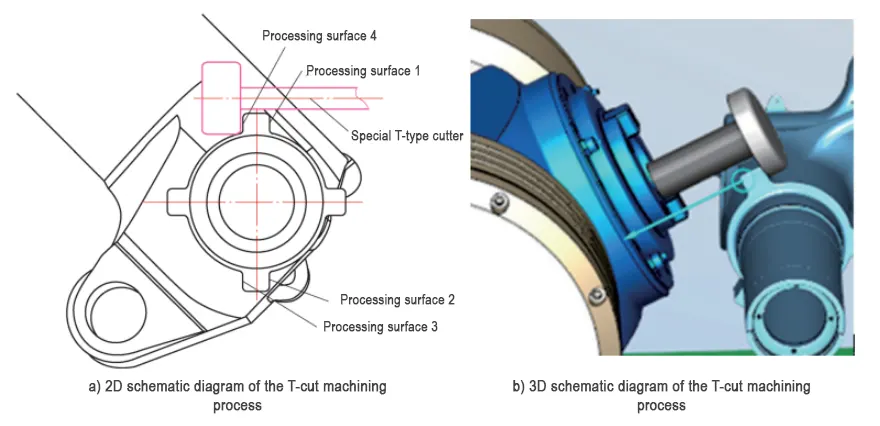
After operators complete the angular rotation, they use a specialized T-shaped tool (see Figure 4) to machine both the front and back surfaces of the same stop key. Since the part has a symmetrical design, one angle allows them to process two stop keys.
After completing the angular rotation, operators use a specialized T-shaped tool (see Figure 4) to machine both the front and back surfaces of the same stop key. Due to the part’s symmetrical design, one angle enables the processing of two stop keys.
After completing the first machining, operators rotate the A-axis and B-axis again to process the remaining two stop keys.
» Other matters.
The rotation of the B-axis during machining gives the specialized “T-shaped tool” for the stop key a relatively long overhang.
When machining with this tool, the root R-angle, the rigidity of the part machining system, and the tool’s own rigidity can combine to create significant vibration marks on the machined surface of the stop key.
These marks reduce product quality. Engineers must therefore strictly control the tool condition and machining process parameters.
(3) Key Processing Process Control Focus
Based on the summary of the processing workflow, operators should prioritize the following aspects during the actual machining of this type of key:
① Compensate for the key processing angle using the actual angular dimensions of the shaft (measured using a coordinate measuring machine) to obtain the angle value closest to the theoretical position.
② During the processing of each key, compensate for the dimensions of each machined surface to obtain the machined values closest to the theoretical dimensions.
③ Experts recommend using circular blades for the specialized “T-shaped tool” and processing no more than two parts per set of blades.
Circular blades provide better dimensional stability when processing this type of key.
Technicians should inspect the tools before processing to ensure the blades remain sharp. They must also strictly control the equipment processing parameters to minimize tool vibration marks and ensure high processing quality.
(4) Calculation Principles for Stop Key Processing Dimensions The principles are as follows.
» Processing point calculation principle.
Programmers compile the CNC program by combining the actual angle of the outer circle where the stop key is located with the machine tool’s rotational position.
They use this data to determine angles and processing points that the production site can use directly. This process outputs the final CNC program..
Engineers use mathematical formulas and macro programs to calculate the starting and ending machining points of the key.
They base the calculations on actual points and angle transformations. This approach enables precise B-axis rotation origin tracking..
After operators install the part on the machine tool and determine its actual position, they first rotate the machined area around the Y-axis to a predetermined angle, establishing the positive direction for angle transformation.
Then, operators rotate the shaft section following the right-hand screw rule, with the thumb pointing toward the end face and the other fingers pointing in the negative direction, to obtain the final position of the key.
Operators calculate the theoretical tool cutting point position for machining the key based on the key width, key length, and the distance from the key’s starting position to the origin.
Operators rotate and project the point onto the new coordinate system using coordinate system projection.
The macro program calculates and obtains the transformed point coordinates.
Calculation program is as follows.
#102=-999.95;(XPVOT AT B=0);Difference between the workbench rotation center and the spindle center along the X-axis in the initial coordinate system
#103=450;(ZPVOT AT B=0); Difference between the workpiece rotation center and the workbench rotation center along the Z-axis in the initial coordinate system
#104=0.0;(BROT FROM B=0); Rotation angle relative to the reference B-axis = 0 for aligning the machined part’s feature area
#105=59;(FINAL COS NO.); Final coordinate system output
#106=0.0;(XOFS AT B=0); Coordinate offset along the X-axis from the tool setting point in the initial coordinate system
#107=0.0;(YOFS AT A=0); Coordinate offset along the Y-axis from the tool setting point in the initial coordinate system
#108=0.0;(BROT FROM B=0); Rotation angle of the B-axis after coordinate offset (rotation around the Y-axis)
#110=0.0;(AROT FROM A=0); Rotation angle of the A-axis after coordinate offset (rotation around the X-axis)
G#101; Activate the machining coordinate system
#111=#[[#4014-53]*20+5201]-#102; Initial coordinate system X-axis coordinate increment when the center of the workbench and the spindle center coincide
#113=COS[#104]; Calculate whether the angle is ±90° or ±270°
IF [#113 EQ 0.0] GOTO666
#114=[#111+#112*SIN[#104]]/COS[#104]; When the calculated angle is ±90° or ±270°, use the following calculation formula
#116=#103
GOTO888
N666
#114=#111*COS[#104]+#112*SIN[#104]; Calculate the X-axis rotation increment when the reverse-calculated angle is not ±90° or ±270°
N888
#117=#114+#106
#118=#107*COS[#110]+#108*SIN[#110]
#119=#116+#108*COS[#110]-#107*SIN[#110]
# 1 2 4 = # 1 1 7 *C O S [ # 1 0 9 ]- # 1 1 9 * S I N [ # 1 0 9 ] + # 1 0 2 #125=#[[#4014-53]*20+5202]+#118
#126=#[[#4014-53]*20+5203]+#119*COS[#109]+#117*S IN[#109]-#103
G10 L2 P[#105-53] X[#121+#124] Y[#122+#125] Z[#123+#126]; Coordinates written
» Principle of angle calculation for machining.
Since the machining of wheel axle stop keys involves angle issues, it is necessary to analyze and calculate the angles before machining.
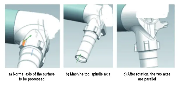
Angle calculation is similar to point calculation in principle, both using coordinate system projection. Angle calculation only requires transforming the vertical vector of the machined plane of the part so that it is parallel to the main axis of the machine tool.
The rotational posture of the part during the machining process is shown in Figure 5.
In the actual machining process, based on different equipment systems, equipment workbenches, machining strokes, and other comprehensive conditions, when compiling the program, it is necessary to consider the actual machining range allowed by the machine tool.
Generally, when machining parts, the A-axis range is -120° to +120°, and the B-axis range is -90° to +90°.
The Excel calculator used to calculate the machining position point compensation and angle is shown in Table 1.

This tool is a macro program command created under the FANUC system statement.
Field technicians can use the machine tool to perform calculations on-site, while process engineers can run this program using VERICUT software to calculate angles.
For convenience in actual use, setting #21 can be adjusted to change the orientation of the wheel axis during actual part processing.
After being optimized according to actual production requirements, this tool can be applied to quickly generate precision machining programs for all similar machining areas, eliminating the need to rely on software for output.
Local macro command program is as follows.
#17=91.69Q – LZ ANGLE); the angle between the wheel shaft and the piston rod, which is a positive value
#3=-45.(C – KJ ANGLE); input the wheel shaft rotation angle, satisfying the right-hand screw rule, with the thumb pointing toward the end face and the other fingers pointing in the negative direction
#11=25.(H – KJ DEPTH); Key thickness, positive value
#19=150.(S – KJ STAT); Position of the key start point and intersection, positive value
#8=188.(E – KJ ENDP); Position of the key end point and intersection, positive value
#7=120.(D – LZ DIAMD); Keyway root outer diameter, positive value
#20=90.(T – TL DIAMD); Tool diameter for machining, positive value
#23=450.(ZOFF AT B=0); Distance from the piston rod center to the workbench rotation center when B=0°
#21=0 (#21=0 A-/A+); The wheel axle can be oriented upward or downward; use #21=0 if oriented upward, otherwise use a non-zero value
N005 G0 G91 G28 Z0.0; Before rotating the workbench, move the workbench away from the tool
N010 G90
N015 G54
N020 IF [#3 GE 0.0] THEN #4=1.0
N025 IF [#3 LT 0.0] THEN #4=-1.0
N030 #3=180.0-#3
N035 #5=-COS[#3]
N040 #6=SIN[#3]
N045 #12=#6*SIN[#17]
N050 #13=#5
N055 #14=#6*COS[#17]
N060 #1=ATAN[#14]/[#13]
N065 #2=ASIN[#12]
N070 IF [#21 NE 0.0] GOTO666; Calculation for shaft neck facing up or down
N075 IF [#2 LT 0.0] THEN #1=#1+90.0; Calculate the angle by which the A-axis should rotate
N080 IF [#2 GE 0.0] THEN #1=#1-90.0; Calculate the angle by which the A-axis should rotate
N085 IF [#2 < 0.0] THEN #2 = -#2; Calculate the angle by which the B-axis should rotate
N090 IF [#21 = 0.0] GOTO888
N666; Calculation for the journal always facing upward
N095 IF [#2 < 0.0] THEN #1=#1-90.0; Calculate the rotation angle of axis A
N100 IF [#2 GE 0.0] THEN #1=180.0+#1; Calculate the rotation angle of axis A
N105 IF [#2 LT 0.0] THEN #2=180.0+#2; Calculate the rotation angle of axis B
» Calculation principle after integrating processing points and processing angles.
Combining the above content, to complete the processing of wheel axle stop keys, it is necessary to integrate the calculation of each stop key point and angle to obtain a comprehensive program for this type of key processing.
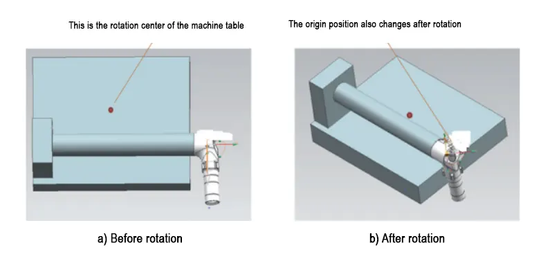
When the part rotates to the processing position, its actual position relative to the rotation before also changes, as shown in Figure 6.
We need to consider the change in the origin in the final program.
» Recommended cutting parameters during machining.
Machinists set the actual cutting parameters based on several factors. These include the rigidity of the machining system, the rigidity of the machine tool spindle, the cutting performance of the selected circular cutting insert, and the properties of the material being machined.
Generally, as load-bearing structural components of aircraft landing gear, ultra-high-strength steel materials are typically used.
The recommended cutting line speed is 30–40 m/min. To ensure the surface roughness of the machined surface, the feed rate is generally set to 0.05–0.08 mm/z.
In actual machining, the cutting parameters can be adjusted within a certain range based on the machining conditions.
Stop Key Inspection Method
Stop key inspection generally involves two aspects: the thickness of the stop key itself and the geometric tolerances of the stop key.
The thickness of the stop key is a general dimension, and conventional micrometers are used for multi-point measurement to ensure that all dimensions are within the tolerance requirements while maintaining a certain degree of stability.
However, the geometric tolerances of the stop key are the focus of inspection.
For this part, the key is primarily inspected for its uniformly distributed angle of 90° ± 10′ and the symmetry requirement of 0.05 mm relative to the wheel shaft center.
Common Inspection Methods for Geometric Tolerances
The above requirements can be inspected using various methods, with the following being commonly used:
Method 1: Coordinate Measuring Machine (CMM) Inspection
First, a coordinate measuring machine is used to establish a measurement coordinate system based on the wheel shaft’s main axis line and the stop key’s end face.
A probe’s “four-point surface sampling” method is employed to measure the positional accuracy and geometric tolerances of the stop keys at various locations on the part.
This measurement method requires high precision from the coordinate measuring machine and has certain tolerance limitations.
The overall measurement process is influenced by the machining quality of the wheel shaft’s outer diameter, and it cannot 100% detect the positional relationships of all mating surfaces between the wheel shaft and the stop keys;
Method 2: Positional Comprehensive Gauge Inspection
The second method involves using a positional comprehensive gauge for inspection.
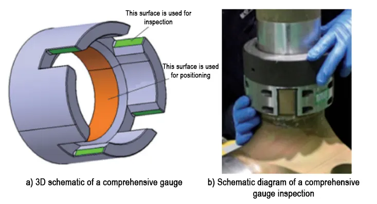
A profile gauge is designed and manufactured, with the outer diameter of the wheel shaft where the stop key is located as the reference, the comprehensive gauge is designed using the “test fitting” method for direct measurement.
Although this method imposes high precision requirements on the comprehensive gauge used for inspection, its manufacturing process is simple and easily meets the precision requirements of the gauge.
Inspectors use the gauge to precisely eliminate the “high points” of each mating surface.
They achieve 100% inspection of the part’s final machining dimensional accuracy and positional accuracy. This process ensures complete quality control.
The design schematic diagram and inspection principle of the comprehensive gauge are shown in Figure 7.
Comparison of Processing Effects Across Different Equipment
Processing Quality
To date, more than 40 products have been processed using a four-axis machining center. After measurement and comprehensive gauge inspection, the processing pass rate was 95.34%.
More than 70 products were processed using a five-axis machining center, with a pass rate of 95.89%.
Both processing methods effectively ensure processing quality. To date, no customer feedback regarding quality issues has been received for the delivered products.
Processing Efficiency
When using a five-axis machining center, after the part is clamped and aligned, there is no need for multiple angle rotations.
The part can be directly positioned and processed using the five-axis machining center’s spindle, with a processing time of approximately 2.2 hours per piece.
The four-axis machining center requires multiple rotations and post-rotation inspections, resulting in longer processing preparation time, with a processing time of approximately 2.6 hours per piece.
Compared to the five-axis machining center, the four-axis machining center has a processing efficiency that is approximately 18.1% lower for this type of stop key, and the processing process requires more attention to details and effort.
Other aspects
Although the machining efficiency of the four-axis machining center is slightly lower, it is significantly cheaper than the five-axis machining center.
Production bottlenecks sometimes occur in common machining equipment in the workshop. The five-axis machining center may also malfunction.
In these situations, the four-axis machining center diverts equipment resources effectively. It ensures both product quality and smooth production.
Conclusion
This paper presents a method for machining stop keys with a horizontal machining center.
It summarizes two tools that assist production. It also demonstrates how to achieve high-precision machining. Manufacturers can widely apply this method to produce stop key-type parts in landing gear integrated structure designs.
FAQ
What is angular geometric tolerance in GD&T, and why is it important?
Angular geometric tolerance controls how precisely a feature’s orientation must be held relative to a reference datum. It ensures components fit and function correctly, especially in complex assemblies like aircraft landing gear.
How do designers define angular tolerances for complex surfaces?
Designers specify a tolerance zone—often bounded by two imaginary planes—within which the feature’s surface or axis must remain. This goes beyond specifying just a fixed angle and allows for manufacturing variability while maintaining function.
What are the common GD&T symbols used to control angular orientation?
The main symbols include Angularity (∠) for general angle control, Perpendicularity (⊥) for 90° angles, and Parallelism (∥) for 0° angular tolerance.
Why is maintaining angular geometric tolerances on complex planes challenging?
Complex surface geometry, multiple inclination changes, machining and setup errors, measurement limitations, and tool deflection all contribute to the difficulty in maintaining precise angular tolerances.
How do five-axis and four-axis machining centers differ in processing stop keys?
Five-axis centers allow machining without multiple re-clamping or rotations, improving efficiency (about 2.2 hours per part), while four-axis centers require multiple rotations and inspections, leading to about 18% lower efficiency but lower equipment cost.
What are the key technical requirements for stop keys on piston rod components?
Stop keys must meet tight dimensional tolerances (as low as 0.02 mm), symmetry requirements within 0.05 mm relative to the wheel shaft center, and angular distribution tolerances of ±10′ to ensure proper function.
How is the machining process controlled to ensure angular tolerance compliance?
Operators use precise clamping, axis alignment, and coordinate transformation calculations combined with specialized tooling like the T-shaped tool to maintain angular accuracy during machining.
What methods are commonly used to inspect the geometric tolerances of stop keys?
Coordinate measuring machines (CMM) with four-point surface sampling and positional comprehensive gauges designed for direct measurement are the primary methods to ensure dimensional and positional accuracy.
How do mathematical formulas and CNC programming contribute to machining precision?
Mathematical models and macro programs calculate exact machining start/end points and angles, enabling precise B-axis rotation tracking and CNC programs tailored to actual part positions, improving accuracy and efficiency.
Why is the use of circular blades recommended for machining stop keys with T-shaped tools?
Circular blades offer better dimensional stability, and limiting processing to no more than two parts per blade set helps maintain sharpness, minimizing vibration marks and ensuring superior surface quality.

