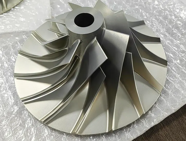
Machining integral impellers is a classic scene in five-axis machining, which fully demonstrates the advantages of five-axis machine tools. It is very difficult to achieve this with four-axis or three-axis machines.
Integral impellers are key components of aviation, aerospace, and marine engines. The main materials for these parts are titanium alloys and high-temperature alloys.
Titanium alloy impellers are mostly used in the cold-end parts of aero-engines, such as fans and pressurizers.
High-temperature alloy impellers are mainly applied in the hot-end parts, like turbines.
These impellers have complex shapes and thin blades, which are time-consuming and inefficient to process, thus resulting in high processing costs.
Therefore, it is very necessary to improve the machining process of the overall titanium alloy impeller, improve the machining efficiency and machining quality, and reduce the machining cost.
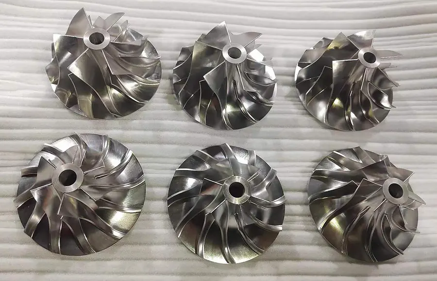
Overall titanium alloy impeller CNC machining process analysis
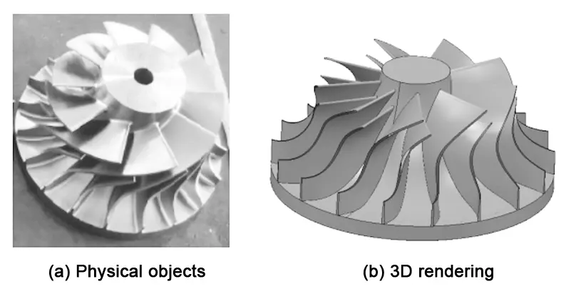
An engine overall titanium alloy impeller shown in Figure 1. Impeller diameter of 180mm, blade length of 42mm, thickness of 2mm, the minimum distance between the blade and the blade on the impeller is only 4.5mm.
The impeller blade is long and thin, with surface distortion and a small blade pitch. If you directly use Powermill’s blade disk programming module to clear the model for roughing, you can realize five-axis linkage roughing of the impeller.
This approach achieves uniform margins and smooth machining trajectories. However, the minimum distance between the blades is only 4.5 mm.
Because of this, only a tool with a diameter of 4 mm can be chosen for roughing. For titanium alloy, which is a difficult-to-machine material, this results in very low roughing efficiency.
Additionally, the slender tool has poor rigidity and is prone to breaking.
Therefore, the impeller machining efficiency is mainly to improve the roughing efficiency, due to the only use of ball-end cutter processing, which exists in the case of low machining efficiency.
After a number of cutting experiments, it was shown that using “3 + 2” fixed-axis machining can achieve the roughing of the impeller.
At the same time, choosing a larger diameter fillet milling cutter and taper milling cutter improves machining efficiency.
Compared to five-axis linkage roughing, there is a great deal of room for improvement in efficiency using this method.
For a general impeller channel, if the curvature of the blade is not very large, two apparent fixed-axis roughing operations can often complete the rough machining of the channel.
However, if the impeller blade surface distortion is too large, the second fixed-axis roughing cannot effectively remove the remaining material.
In this case, it is necessary to use three fixed-axis roughing operations to complete the rough machining of the runner.
Three different working coordinate systems are defined, each fully capable of removing the runner blank from its viewpoint.
Then, the Z-vectors of these three coordinate systems are used to define the tool axis vectors for the three fixed-axis roughing tool paths.
After the completion of roughing, the impeller module of Powermill is used for the finishing of the hub and blades. In summary, the overall titanium alloy impeller CNC machining process program developed is shown in Table 1.

Impeller CNC machining programming process
Programming preparation
Smooth program preparation before the need for processing parts for some of the necessary preparatory work, such as setting up the machining coordinate system, the establishment of blanks, the establishment of machining tools and so on.
Establishment of blank
In order to reduce the machining time of the impeller, the blank can first be machined in place on the CNC lathe.
The five-axis machining then only processes the material in the runner.
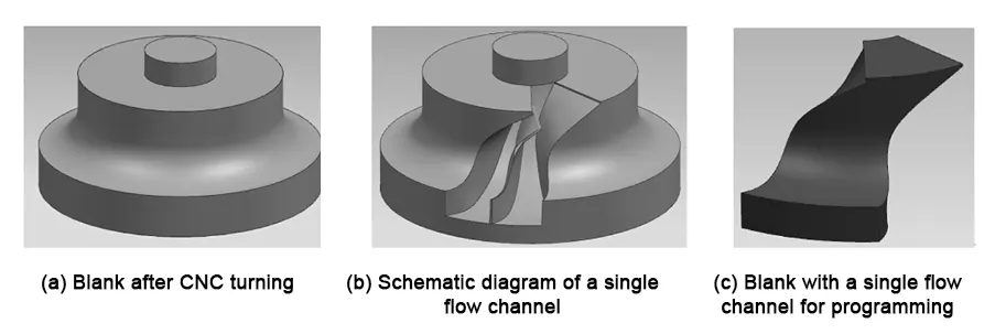
Therefore, the CNC lathe can first machine the impeller’s end face, step surface, meridian surface, and other related surfaces. This initial machining is shown in Figure 2 (a).
According to the “3 + 2” fixed-axis roughing process, the roughing of the runner groove is roughing one by one, so the programming only needs to create a runner blank, as shown in Figure 2 (b), Figure 2 (c).
Create a blank in the NX software settings after export, in Powermill through the “triangle model” to open the blank, the specific operation steps are as follows:
Click the toolbar “blank” button, the system pop-up ‘blank’ dialog box, select the “triangle” blank, specify the path to open the blank to enter the blank.
Tool selection
CNC machining tools need good rigidity and high precision. They also require dimensional stability and high durability.
Additionally, they must have effective chip-breaking and chip removal performance. At the same time, easy installation and adjustment are necessary.
All these features are required to meet the demands of high-efficiency CNC machine tools.
Based on the machining requirements of this impeller, a rounded blade type milling cutter with D10R2 is used for roughing. R3T3 and R2T3 taper milling cutters are used for the second and third roughing and finishing.
This selection aims to improve the strength of the tool. These tools are shown in Figure 3.
Programming needs to be set according to the actual tool size and the size of the shank of the tool and clamping, in order to ensure that the preparation of the tool track can be used for actual machining.
“3 + 2” fixed-axis roughing
Roughing of parts is done to remove excess material as quickly as possible. However, due to the impeller’s curved surface distortion and small blade pitch, five-axis linkage roughing faces challenges.
The maximum diameter of the available tool is only 4 mm, resulting in low roughing efficiency. Additionally, the machine tool’s rotary axis has a large swing amplitude.
This causes poor machine tool stability and vibration. As a result, tool wear is exacerbated and the service life of the tool is shortened.
Therefore, the “3 + 2” fixed-axis roughing method is adopted to reduce the movement of the rotary axis and greatly improve the efficiency.
After analyzing and verifying many times, it takes three times to remove the excess material, the first roughing tool D10R2 is used to remove the spacious part of more material and add it to the residual model as the blank for the next roughing;
Then, use the R3T3 taper milling cutter to change the directional angle for the second roughing. Add this to the residual model.
Because the minimum distance between the blades is only 4.5 mm, it is also necessary to use the R2T3 taper milling cutter for the third roughing. Set the parameters as follows: Tolerances at 0.1, Z-axis down tool using oblique feed.
Enable ProfileSmoothing (profile smooth). Set CornerRadius (corner radius TDU) to 0.1. Set SmoothingAllowance (smooth margin) to about 15%.
Three open roughing parameter settings and toolpath trajectory and machining results shown in Figure 4 to Figure 6.

After completing the above steps, one runner roughing operation can be finished. The roughing of the remaining runners can be achieved by applying the same toolpath transformation.
Specifically, the toolpath is rotated by 40° to carry out the roughing of the next runner.
This method of roughing the toolpath may appear a little messy. However, the processing efficiency is very high.
Based on actual machining verification, this roughing method saves about 70 minutes compared to five-axis linkage roughing. It greatly improves productivity and extends the service life of the tool.
As a result, it reduces costs and offers high practical value.


Impeller finishing
After three times of rough machining, the excess material is basically removed, and the impeller module of Powermill can be programmed directly next.
Considering the uneven margin left by rough machining, the blade is finished using a layering method.
In this process, the three blades of one runner—namely the left blade, right blade, and diverter blade—are layered simultaneously.
This approach helps reduce collisions between the side edge of the tool and the uneven blank material. It also ensures the stability of the machining process.
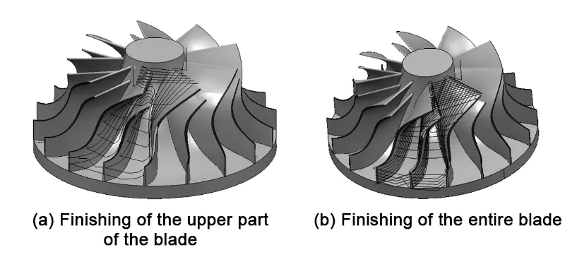
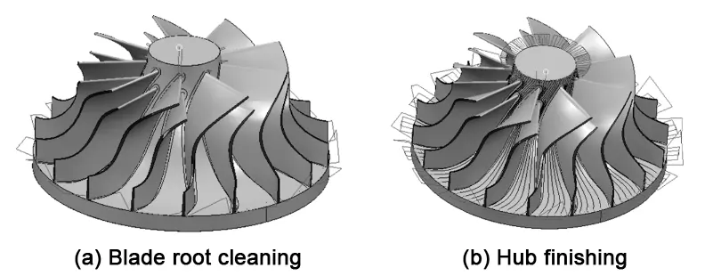
Therefore, during the finishing process, the upper part of the blade is first finished using the R3T3 tool (as shown in Fig. 7(a)).
Next, the areas that cannot be processed with the R3T3 tool are machined using the R2T3 tool (as shown in Fig. 7(b)).
Finally, the blade root is cleared for machining (as shown in Fig. 8(a)), and the hub (runner) is finished (as shown in Fig. 8(b)).

Fig. 6 Thrid roughing
Post processing and Vericut simulation cutting verification
Vericut simulation software is used to simulate the cutting verification, to confirm that the program code is correct, the program will be copied to the CNC machine tool for actual processing.
The use of Powermill software post-processing files have been written to generate a good toolpath trajectory CNC machine tool machining program code.
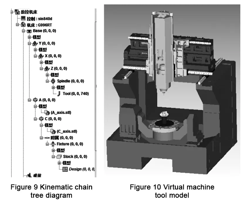
In Vericut software, a simulation model of the G996RT five-axis machining center is built. The motion tree diagram and virtual machine model are shown in Figure 9 and Figure 10.
The program code is then loaded into the simulation. Next, the tool, coordinate system, and other parameters are set up for the simulation process.
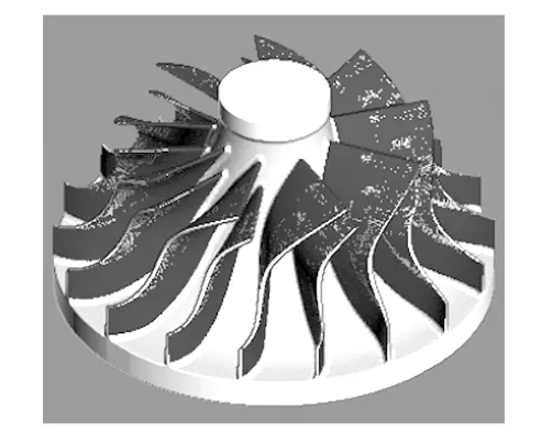
The simulation results are presented in Figure 11. After the simulation results (cutting model) are obtained, a comparison and analysis should be carried out.
This is done to check whether the parts are overcut, undercut, or have other machining issues. If the results of the comparative analysis are not satisfactory, adjustments must be made.
This may involve modifying or replacing the CNC machining program.The process continues until the cutting model is consistent with the design prototype.
Conclusion
The aim is to reduce machining costs, improve machining efficiency, and enhance the quality of parts.
To achieve this, a new roughing process protocol is proposed.
This involves using different angles and multiple passes of the “3 + 2” fixed-axis roughing method to remove most of the material.
This approach addresses the problem of high machining costs associated with five-axis CNC machine tools.
The problem of high machining cost of five-axis CNC machine tools is solved, and the layering method realizes the machining of the whole titanium alloy impeller with high speed and high feed on five-axis machine tools.
The actual processing shows that this technology program can complete the CNC machining of the whole titanium alloy impeller with high efficiency and high quality.

