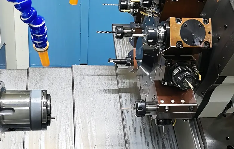
Automation production is the use of advanced technologies such as robotics, computer control systems, and intelligent machines to perform production tasks with minimal human intervention.
It increases efficiency, improves product quality, reduces labor costs, and enables high-volume, consistent output.
This article takes the plunger joint, a typical part of a pipe fitting, as an example to discuss the automated processing of stainless steel pipe fitting parts.
Pipe fitting products serve as core components connecting conduit assemblies within spacecraft system piping networks.
Their quality and performance directly determine the functionality, sealing integrity, and safety of these systems.
With the continuous advancement of the aerospace industry, the variety and volume of pipe fitting requirements have surged dramatically.
Traditional discrete CNC machining methods can no longer meet the demands for diverse, rapidly customized pipe fitting solutions. Flexible automated production has thus become an essential choice.
Analysis of Pipe Fitting Product Characteristics
Piston fittings: 37 specifications, diameters 16–32 mm, lengths 32–60 mm; Threaded fittings: 8 specifications, diameters 28–35 mm, lengths 50–59 mm;
Outer sleeve nuts: 36 specifications, diameters 28–37 mm, lengths 19–23.5 mm.
A typical pipe fitting product is shown in Figure 1.
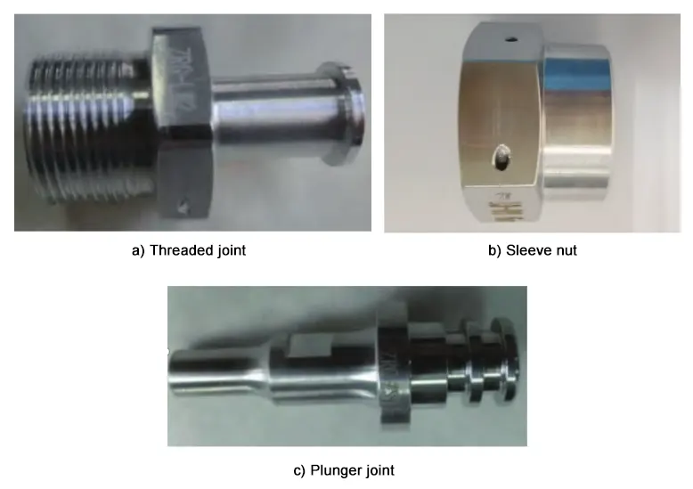
This article uses the typical plunger joint as an example.
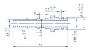
Product requirements include an outer diameter of ϕ13 -0.016
–0.034 mm, ϕ8 +0.1
0 mm, a sealing groove dimension of ϕ10 0
-0.04 × 2.7 +0.06
0 mm, a parallel groove dimension of 6 mm × 9 0
-0.2 mm, and through-hole dimensions of ϕ6 +0.05
-0.0.05 ×58 mm. The product demands high precision.
The plunger fitting is shown in Figure 2.
Product Development Process Flow
The product demands high-quality raw materials and dimensional accuracy. Non-destructive testing is scheduled after material receipt and blanking to ensure raw material quality.
To control product deformation, internal wall inspection via endoscopy is performed throughout roughing, finishing, and post-machining stages. A typical pipe joint product process flow is shown in Figure 3.
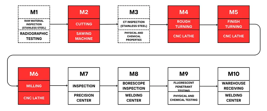
Based on machining requirements, detailed dimensional processing plans are established: external diameters and sealing grooves are turned, parallel grooves are milled, and through-holes are drilled and reamed.
Functional Design of Automated Production Equipment
Pipe fittings share similar dimensions and are classified as small shaft-type metal components, primarily processed through turning with supplementary milling.
Raw materials consist of slender rods, suitable for automated processing via a pusher mechanism for loading, in-machine cutting, and automatic repositioning/clamping.
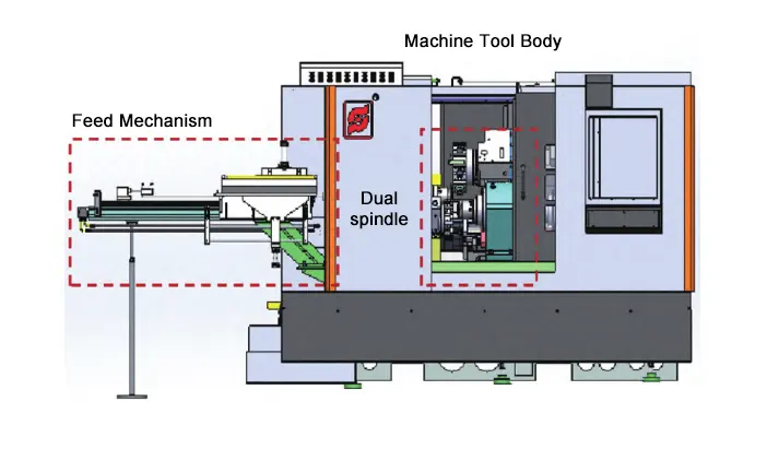
The dual-spindle equipment enhances processing efficiency while enabling in-machine automatic clamping.
By adding automatic feeding and unloading devices, the system achieves automated part handling.
Standardized processes and automated CNC programs drive the automated workflow: “Loading → Station 1 Processing → Deburring → Alignment/Clamping (dual clamping) → cutting → Station 2 machining → deburring → unloading.”
The automated production cell incorporates a master control system for managing production tasks and automatically distributing/calling CNC programs.
The equipment’s exterior is shown in Figure 4.
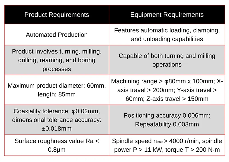
The part processing involves turning, milling, drilling, reaming, and boring operations.
Based on product dimensional requirements, the functional modules of the automated production equipment must be analyzed to complete the equipment design and construction.
The functional analysis of the automated production equipment is shown in Table 1.
Design of Automated Production Process Flow
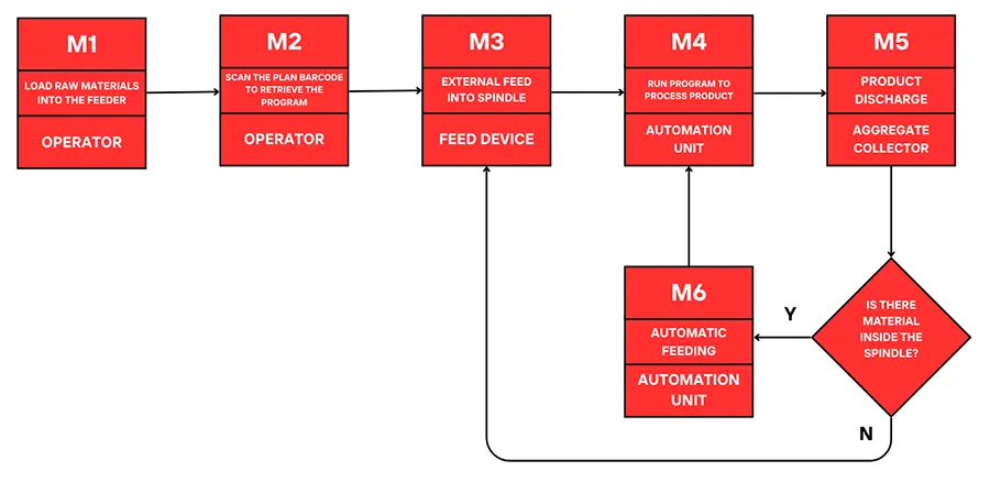
The automated production process begins with material feeding to the equipment via an automatic feeding device.
Within the equipment, program control automates clamping, machining, and cutting operations. After processing, the finished product is automatically unloaded, initiating a continuous cycle.
The CNC program sets the processing quantity as a variable, with the number of program cycles determined by the production plan. The automated internal production cycle flow is illustrated in Figure 5.
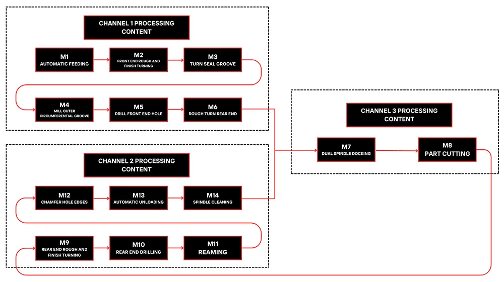
The automated production process for piston rod joints involves automatic feeding of logistics module parts and unloading of finished parts.
Parts are fed to Channel 1 spindle for front-end rough/finish turning, sealing groove turning, outer groove milling, front-end hole drilling, and rear-end rough turning.
Channel 2 spindle performs rear-end rough/finish turning, drilling, reaming, hole chamfering, automatic unloading, and spindle cleaning.
The dual-spindle, dual-channel configuration enables automatic part alignment and synchronized processing across both channels.
This effectively eliminates automation challenges caused by workpiece flipping and secondary clamping.
Channel 1 and Channel 2 process distinct sections simultaneously, significantly enhancing machining efficiency.
The plunger joint machining flow is illustrated in Figure 6.
Optimization
Material Property Analysis
The pipe fitting material is 1Cr18Ni9Ti, exhibiting machinability properties at only 50%–70% of 45 steel. Classified as a difficult-to-machine material, it primarily manifests as poor chip breakage and a tendency toward chip entanglement, severely impacting automated processing.
Additionally, tools wear rapidly. When machining stainless steel, the contact length between chips and the rake face is approximately 65%–70% that of carbon steel, causing stress concentration near the cutting edge and increasing tool chipping risk.
Furthermore, cutting heat concentrates near the cutting edge, resulting in high cutting temperatures, accelerated tool wear, and elevated cutting forces.
Orthogonal Test Design for Cutting Parameters
Based on stainless steel’s machining characteristics and automated processing requirements, cutting parameter indicators for the piston joint were established across three aspects: cutting time, chip morphology, and machine tool status.
Cutting time corresponds to machining efficiency, chip morphology is a prerequisite for automated processing, and stable machine operation ensures dimensional accuracy and surface quality.
Cutting process experimental design typically involves single-factor experiments and orthogonal experiments.
Single-factor experiments allow only one variable to change while others remain constant.
Though more straightforward and more convenient, they treat factors as independent, yielding results without interaction effects.
In contrast, orthogonal experiments enable multi-factor, multi-level analysis.
This scientific and efficient experimental method fully accounts for interactions between factors, reducing the number of trials while facilitating data processing and research.
We selected the orthogonal experimental design method to investigate how cutting parameters affect cutting time and machining results for piston rod joints.
We investigated how cutting parameters influence product cutting time, chip morphology, and machine tool status through analysis.
Cutting speed, feed rate, depth of cut, and dwell time serve as the experimental factors for the study.
Based on standard stainless steel cutting parameters and engineering application manuals, the cutting parameters were designed as follows:
Cutting speed v = 40–60 m/min, feed rate f = 0.2–0.3 mm/r, depth of cut ap = 0.7–1.2 mm. Dwell time t0 = 0.2–0.3 s.
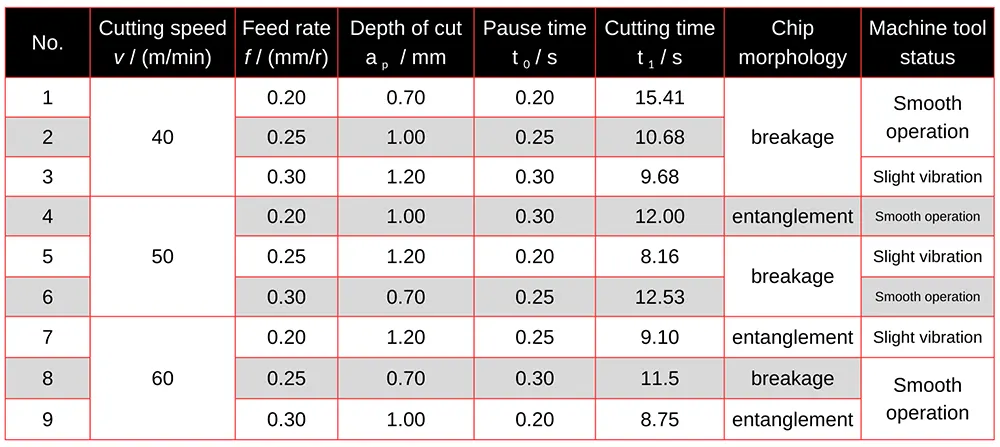
Orthogonal experimental design was employed. The experimental plan and results are presented in Table 2.
Analysis of Orthogonal Test for Cutting Parameters
Our analysis of the plunger joint orthogonal test, based on machine tool operating status, chip morphology, and processing time, shows that automated production must meet fully automated machining requirements.
If chips entangle and the machine tool vibrates during processing, the operation fails to meet the requirements.
> Parameter Screening and Exclusion
First, exclude processing parameters from groups 3, 4, 5, 7, and 9. Subsequently, determine the optimal levels and conduct range analysis for the orthogonal test.
Range analysis assesses the magnitude and trend of each factor’s influence on the target value.
Let Yjm denote the test indicator corresponding to factor m at level j, and Kjm denote the average value of Yjm.
Range R = Kjmmax – Kjmmin. A larger range indicates a greater influence of that factor on the target value.
Based on the values of Kjm and range R, determine the optimal level and optimal combination for the jth column factor.
> Cutting Time Analysis
The range analysis for cutting time is shown in Table 3.
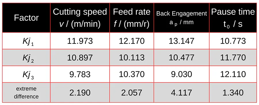
Through range analysis, the factors affecting cutting time in descending order of influence are: depth of cut, cutting speed, feed rate, and dwell time.
The conditions for the shortest processing time are: cutting speed v = 60 m/min, feed rate f = 0.3 mm/r, depth of cut ap = 1.2 mm, and dwell time t0 = 0.2 s.
> Multi-Objective Optimization for Stability and Efficiency
The above analysis reveals a clear trade-off between minimizing cutting time, maintaining stable machine operation, and achieving good chip formation.
This demonstrates that single-factor optimization cannot meet practical production requirements, necessitating multi-objective optimization parameter combinations for experimentation.
First, optimizing the depth of cut to 1 mm simultaneously optimizes cutting time and machine stability.
Second, the cutting speed is set to 40 m/min. For stainless steel products, higher cutting speeds compromise machining stability.
The feed rate is set to 0.3 mm/r, and the pause time to 0.3 s. The combination of a higher feed rate and machining pauses facilitates chip breaking during stainless steel processing, ensuring stable automated operation.
Through establishing automated production cells and optimizing process flows—replacing manual operations with automated loading and unloading—production efficiency has significantly improved.
Pipe fitting production efficiency comparisons are shown in Table 4.

Calculations show that the automated unit enables automatic feeding, continuous turning, and milling operations, reducing clamping and handling steps.
Product processing time is shortened from 115 min to 57 min, doubling production efficiency. One operator can simultaneously manage three machine tools, boosting processing efficiency by over fivefold.
Conclusion
1) Focus on establishing product development processes tailored to the material properties, structural characteristics, and dimensional accuracy requirements of pipe fittings.
Complete the functional design and construction of automated production equipment. Develop unit operation workflows to achieve single-setup machining for each product.
2) Employ orthogonal experiments during production to continuously optimize process parameters, enabling efficient pipe fitting manufacturing.
Compared to traditional methods, integrated turning-milling automated processing achieves over fivefold improvement in machining efficiency.
3) Practical production demonstrates the feasibility of this automated turning-milling integrated solution for complex, high-precision pipe fitting components.
It serves as a reference for automated manufacturing enterprises producing aerospace products characterized by diverse varieties, small batches, and high precision.
FAQ
How to automate production of turning and milling?
Automated production in CNC machining uses robotics, computer control systems, and intelligent machines to perform manufacturing tasks with minimal human intervention, increasing efficiency and ensuring consistent, high-quality output.
Why is automation important in pipe fitting manufacturing?
Automation ensures precision, reduces labor costs, minimizes human error, and enables mass production of high-precision pipe fittings that meet the demanding requirements of aerospace and other industries.
What are the main challenges in machining stainless steel pipe fittings?
Stainless steel is difficult to machine because of poor chip breakage, high cutting temperatures, and rapid tool wear. These issues can cause chip entanglement and vibration, reducing machining stability and efficiency.
How does automated production improve pipe fitting quality?
Automated systems maintain consistent clamping forces, monitor dimensional accuracy in real time, and reduce deformation through precise control, ensuring better sealing performance and overall product reliability.
What machining processes are used in automated pipe fitting production?
Typical processes include turning, milling, drilling, reaming, and boring, performed in a fully integrated sequence with automatic part feeding, clamping, and unloading for continuous operation.
What are the key cutting parameters for automated stainless steel machining?
Key parameters include cutting speed, feed rate, depth of cut, and dwell time. Optimizing these parameters through orthogonal experiments ensures stable operation, good chip formation, and reduced cycle times.
How do dual-spindle CNC machines improve efficiency?
Dual-spindle machines allow simultaneous machining of both ends of the workpiece, eliminate secondary clamping, and synchronize operations, significantly reducing cycle time and boosting productivity.
What role do orthogonal experiments play in process optimization?
Orthogonal experiments analyze how different cutting parameters interact, allowing manufacturers to find the optimal combination that minimizes machining time while maintaining stability and part quality.
How much can automation reduce production time?
Automated production can cut processing time by over 50%, reduce manual handling steps, and allow one operator to oversee multiple machines, increasing productivity by more than fivefold.
Why is automated machining ideal for aerospace pipe fittings?
Aerospace components require tight tolerances, reliable sealing, and structural integrity. Automated machining ensures repeatability, precision, and efficiency — critical factors for aerospace applications.

