Processing plays a decisive role in the manufacture of complex parts. With continuous technological advancement, the structures of components for precision instruments, aerospace, aviation, military equipment, and many other devices are becoming increasingly intricate.
Because of their unique application environments, most of these parts adopt irregular shapes. They not only require high-dimensional accuracy but also must meet stringent geometric tolerances.
These irregular parts are often difficult to position and clamp using universal fixtures, necessitating the design of specialized tooling fixtures.
During machining, single-setup positioning often fails to accommodate multi-surface processing, while process factors significantly impact both product quality and production efficiency.
Consequently, process improvement and optimization have become critical focal points in industrial production and academic research.
Part Characteristic Analysis
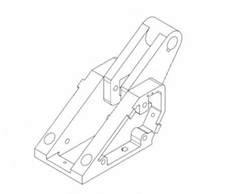
Here, we illustrate the importance of the entire process using a hinge—a non-standard part commonly found in aerospace vehicles (Figure 1)—as an example.
The part exhibits an irregular structural form overall. Its sides and bottom contain multiple holes of varying specifications, while the square through-cavity in the middle section and the side cavities all require precision machining.
Developing a machining process typically requires a meticulous examination of technical parameters, including the part’s geometry, material properties, surface roughness, and geometric tolerances.
Engineers then thoroughly analyze the part’s process requirements and determine a rational machining sequence.
Figure 2 illustrates the process flow adopted based on the machining characteristics of the hinge.

Figure 2 reveals the inherent complexity of this part’s manufacturing sequence.
When machining complex, multi-faceted parts, the optimal approach is to utilize multi-axis CNC machines for cutting operations to ensure high-quality machined surfaces.
Therefore, engineers selected the five-axis machining center DMU60 phi-dyu as the CNC machining equipment.
Given the extensive scope of hinge manufacturing processes, this paper focuses on process improvements during the machining center stage 80 in the flowchart.
Improvements primarily involve optimizing fixture structures and machining sequences during CNC processing.
Processing Difficulties
Stage 80 of the process flow primarily reflects the following processing challenges:
1) Irregular shape, making clamping and positioning difficult. Engineers cannot use generic fixtures, so they must design specialized tooling.
2) The manufacturer uses Ti-6Al-4V material for the part, which has low thermal conductivity, high chemical reactivity, and a small elastic modulus. It can operate stably over extended periods within a temperature range of 400–500°C.
At room temperature, it exhibits a yield strength of 825 MPa and a Rockwell hardness of 32–38 HRC, classifying it as a typical difficult-to-machine material.
3) After undergoing six primary machining stages—CNC turning, wire cutting, CNC milling, heat treatment, CNC milling, and slow-speed wire cutting—the part achieves its overall external shape and intermediate square through-cavity.
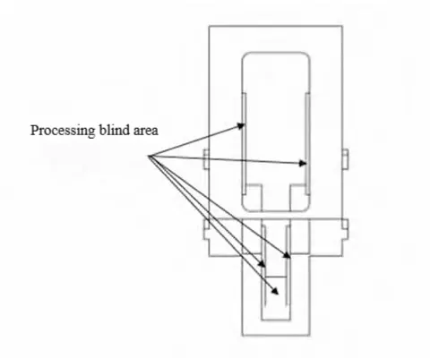
However, due to dimensional constraints and technical limitations, processing blind spots emerged during machining (as shown in Figure 3).
Therefore, engineers must finish the part’s external dimensions at process stage 80 and perform secondary machining for these blind areas.
Analysis of Process Improvement Requirements
At process stage 80, a dual-pronged strategy was adopted to ensure part quality and enhance machining efficiency.
First, during milling operations, a sequential machining approach was implemented: rough milling → semi-finish milling → finish milling.
Second, superior carbide cutting tools were adopted to reduce cutting forces, heat generation, and workpiece deformation.
High-pressure, high-flow cutting fluids complemented these to maintain thermal stability throughout the machining process.
To prevent stress-induced deformation in hinges during processing, a stress-relief treatment was applied at the post-process stage 40 to eliminate residual stresses.
The practical implementation of these measures relies on rational fixture coordination.
Improved Fixture Design
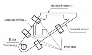
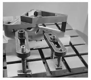
The original fixture employed the structure shown in Figure 4, utilizing four clamping plates with locating holes at the machined side cavities.
While this fixture design is simple to manufacture and achieves clamping functionality, it exhibits significant drawbacks during actual machining.
The process becomes exceptionally cumbersome when automation levels are low.
For instance, after machining surface 3, the clamping plates on the side containing surface one must be removed and relocated to the cavity for surface three before machining surface one can commence.
Similarly, when machining surface 2, all clamping plates on the surface two side must be removed to secure surfaces 1 and 3 with clamping plates. This necessitates disassembling the clamping plates for each surface machined.
After removal, clamping plates must be reinstalled according to the new machining position, followed by realignment and adjustment before processing the target surface.
During clamping, operators cannot consistently apply an identical force to the clamping plates, causing inconsistent deviations from the reference axis with each setup.
Repeated clamping makes achieving pinpoint accuracy difficult, compromising part quality. The original fixture layout is shown in Figure 5.
Design Principles for Fixture Improvement
Addressing the shortcomings revealed during practical use of the original fixture, improvements were made to achieve single-setup machining of multiple features while ensuring all machining requirements, dimensional accuracy, and geometric tolerances are met.
During the improvement process, in addition to considering the fixture’s impact on hinge product quality, efforts were made to enhance precision by ensuring fixture positioning, defining reference points, and accounting for machine travel limits as well as potential interference between tools, workpieces, and fixtures.
Per machining specifications, the workpiece requires six degrees of freedom to be constrained.
After comprehensively evaluating positioning stability and clamping convenience, a one-surface-two-pin locating structure was adopted for the fixture.
Considering the factory’s actual conditions, the improved fixture utilizes two pre-machined φ6 mm holes as locating holes, combined with a locating method integrating cylindrical pins and diamond-shaped pins.
The cylindrical pins restrict movement along the X and Y axes, while the diamond-shaped pins limit rotation around the Z axis.
The large flat surface constrains movement along the Z axis and rotation around both the X and Y axes, thereby achieving the required six degrees of freedom restriction.
Despite its complex hinge structure, the fixture weighs approximately 1.539 kg, facilitating manual insertion of the locating pins.
> Calculation Process
The calculation process for parameters related to the cylindrical and diamond pins is as follows:
1) Determine the center distance Lx between the two locating pins and its tolerance δLx.
Lx = Lg (1)
δLx = (1/5)δLg ~ (1/3)δLg (2)
Where: Lg is the workpiece center distance, taken as 45 mm; δLg is the workpiece center distance tolerance, taken as 0.10 mm.
Calculations yield a δLx range of 0.02–0.03 mm. In this design, δLx is set to 0.02 mm.
2) Determine the cylindrical pin diameter d1 and tolerance zone designation δd1.
d₁ = D₁ (3)
Where: D₁ is the minimum diameter of the reference hole for the cylindrical pin. When d₁ = 6 mm, the tolerance zone designation δd₁ is selected as g6.
3) Calculate the widths b and B of the rhombic pin.
Selection of b and B is shown in Table 1. With the minimum diameter D₂ of the rhombic pin reference hole being 6 mm, when b = 2 mm, B = D₂ – 0.5 = 5.5 mm.

4) Calculate the minimum clearance Δ2 between the diamond pin and the reference hole.

Where: Δ1 is the clearance between the cylindrical pin and the reference hole.
Taking Δ1 = 0.006 mm, b = 2 mm, and D2 = 6 mm, the calculation yields Δ2 = 0.08 mm.
5) Calculate the rhombic pin diameter d2.
d2 = D2 – Δ2 (5)
Select tolerance zone designation h6 for d2, yielding d2 = 5 mm.
Implementation of Fixture Improvements
The simplified diagram of the improved fixture is shown in Figure 6.
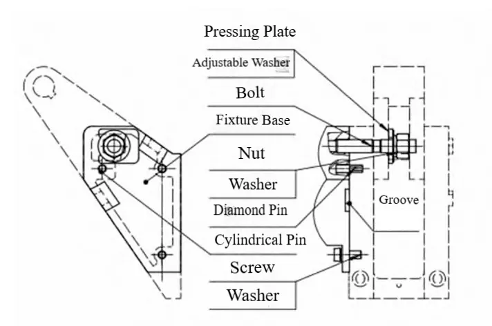
In the front view, two φ6mm holes serve as locating holes. The center distance Lx between the two locating pins is 45 ± 0.02 mm.
The hinge positioning is achieved through a combination of cylindrical and diamond-shaped pins.
In the left view, the clamping plate, washers, bolts, nuts, and screws all serve auxiliary positioning and clamping functions.
The fixture base is designed with mounting holes for bolts and screws. Bolts and screws connect to the hinge via the hinge itself and the pre-machined base holes.
Specifically, the groove in the left view avoids the hinge boss, preventing interference.
The clamping plate features a notch that enables rapid removal when the nut is loosened.
This design aims to streamline subsequent part removal and installation processes, thereby reducing fixture setup time.
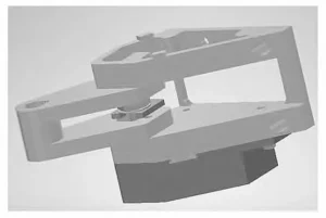
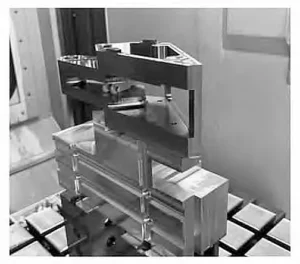
To validate the design feasibility, a 3D simulation of the fixture was conducted (as shown in Figure 7), with the improved fixture’s on-site configuration depicted in Figure 8.
Process Improvement Strategy
During the machining of irregular parts, selecting appropriate cutting tools is essential to ensure dimensional accuracy.
Process flow stage 80 utilized 12 tool types, including four drill bit specifications (D1.6L15, D3L15, D3.3L15, D5L40) and milling cutters (specific models listed in Table 2).
A large number of tools, when combined with an inefficient process sequence, would increase the frequency of tool changes, prolong part processing time, and reduce production efficiency.

Before tooling improvements, structural limitations required designing the process route based on machining surfaces (specific surfaces shown in Figure 4).
This meant completing all features on one surface before moving to the second surface, then proceeding to the third surface.
This process was repeated until all features on every surface were completed. This design approach presented issues: for instance, a drill bit could only machine holes on one surface at a time.
Holes of the exact specification on another surface could not be machined during this operation and had to wait until that surface was processed, leading to increased tool changes.
After tooling improvements, the process route design adopted the tool as the fundamental unit.
Before machining, features are analyzed and grouped. Operations that can be completed with the same tool are scheduled consecutively. This means using one tool to continuously machine all machinable features across multiple surfaces until all features are finished before a tool change.
During machining, the workpiece table or spindle rotation enables a single tool to process multiple surfaces. This method significantly reduces the need for tool changes, thereby shortening the total part processing time.
Effects of the Improvement
With the original fixture, frequent clamping plate loading/unloading resulted in low automation levels and numerous inspection steps, leading to prolonged part processing times.
Following fixture improvements, incorporating probe programs into the programming enables automatic straight-line calibration, setting X, Y, and Z coordinates, and performing automatic origin measurement.
Even if deviations occur during installation, the probe program can correct them and adjust the center coordinates, enabling machining to continue without requiring a reset of coordinates.
This improvement achieves the goal of multi-surface machining with a single clamping operation.
Simultaneously, eliminating additional inspection steps ensures machining quality while reducing overall part processing time effectively.
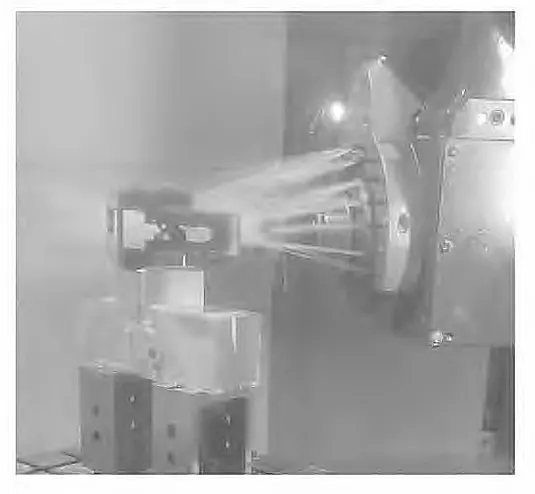
The post-improvement machining scene is shown in Figure 9.
Conclusion
The improved fixture enables automatic straight-line alignment and automatic origin measurement, ensuring reliable positioning.
Compared to the original fixture design, it eliminates the need for frequent clamp plate removal, significantly reducing operational complexity, minimizing auxiliary time, enhancing automation levels, and resolving challenges associated with single-setup and multi-surface machining.
The post-improvement process design shifts from surface-based units to tool-based units, reducing tool changes and boosting machining efficiency.
The practical application of the DMU60phi-dyu machining center for processing irregular hinge parts validated the feasibility of this fixture improvement, resulting in a 30% reduction in machining time at Process Flow Stage 80.
FAQ
Why is the machining process so critical for irregular or special-shaped parts?
The machining process plays a decisive role because irregularly shaped parts—such as those used in aerospace, aviation, and defense—require not only high-dimensional accuracy but also strict geometric tolerances. Without optimized processes, positioning errors, deformation, and efficiency losses occur, making process design the key to part quality and cost-effectiveness.
What makes irregular aerospace parts challenging to clamp and position?
Irregular aerospace parts cannot be secured with standard universal fixtures because of their non-standard shapes and multi-surface features. They require specialized fixture design to achieve six degrees of freedom constraint, ensure stable positioning, and allow multi-surface machining in a single setup.
Why is Ti-6Al-4V considered a difficult-to-machine material?
Ti-6Al-4V has a low thermal conductivity, high chemical reactivity, and a relatively small elastic modulus. It maintains high mechanical strength at elevated temperatures (400–500°C) with a yield strength of 825 MPa and hardness of 32–38 HRC. These properties cause rapid tool wear, heat concentration, and potential deformation, making advanced tooling and cooling essential.
What were the main processing difficulties in machining the aerospace hinge part?
The difficulties included:
Irregular shape complicating clamping and positioning.
Ti-6Al-4V’s poor machinability.
Blind areas remaining after previous machining steps that required secondary machining.
These factors demanded fixture and process route improvements at stage 80 of the machining sequence.
How did the improved fixture design address accuracy and efficiency issues?
The improved fixture used a one-surface-two-pin locating structure with cylindrical and diamond-shaped pins. This provided precise six degrees of freedom constraints, minimized clamping errors, and enabled multi-surface machining in a single setup. The result was higher positioning accuracy, reduced re-clamping operations, and more stable machining outcomes.
What role did probe programs play in the improved machining process?
Probe programs automated straight-line calibration, origin measurement, and coordinate correction. Even if slight installation deviations occurred, the system corrected them without requiring manual resetting, greatly enhancing automation, reducing inspection time, and improving consistency in machining results.
Why was a tool-based machining sequence more efficient than a surface-based one?
The tool-based approach grouped machining operations by tool rather than surface. This allowed one tool to process multiple surfaces consecutively, significantly reducing tool change frequency, improving machining continuity, and shortening overall cycle time compared to the surface-by-surface method.
How did cutting tool selection contribute to machining Ti-6Al-4V hinges?
Carbide cutting tools with superior heat resistance and wear resistance were chosen to reduce cutting forces, minimize deformation, and handle Ti-6Al-4V’s challenging properties. Combined with high-pressure, high-flow cutting fluids, these tools maintained thermal stability and prolonged tool life.
What measurable benefits did the fixture and process improvements deliver?
By enabling single-setup, multi-surface machining and reducing tool changes, the improved fixture design and process optimization shortened the machining time at Process Stage 80 by 30%. At the same time, machining accuracy and part quality improved, while automation levels and process stability were enhanced.
How can fixture and process optimization influence aerospace manufacturing competitiveness?
In aerospace manufacturing, where irregular parts and difficult materials like titanium alloys are common, optimized fixtures and process strategies reduce production time, minimize waste, and ensure dimensional accuracy. These improvements directly enhance production efficiency, reduce costs, and strengthen competitiveness in precision-critical industries.

