In the drilling process, “L/D” refers to the ratio of the depth of the hole to the diameter of the hole being machined (i.e., L/D). Generally, we call holes with an L/D ratio greater than 10 “deep holes.”
As parts become more complex and integrated, deep hole machining has become more common, and manufacturers widely use drilling technology.
The emergence of deep hole drilling tools such as deep hole twist drilling, gun drilling, BTA drilling, spray suction drilling, and DF drilling has advanced machining capabilities.
Additionally, developing new deep hole machining technologies, including mechanical vibration drilling, ultrasonic vibration drilling, hydraulic vibration drilling, and electromagnetic vibration drilling, has further enhanced the process.
As a result, deep hole machining capability has significantly improved compared to the past.
However, deep hole machining has its own specificity. The drill bit works under semi-closed conditions when it enters the workpiece.
In actual processing, this creates more restrictions, as one cannot directly observe the tool cutting situation.
Cutting heat does not spread easily, so effective cooling must be applied. Chip removal is difficult, and the drill rod needs to have sufficient rigidity, among other factors.
These difficulties cause large differences in the practical application of the effect.
They also require combining the actual processing of parts for verification and summary.
Typical Deep Hole Machining Problems
A typical hydraulic actuator cylinder barrel’s local structure is shown in Figure 1. The part is made of 30CrMnSiA and has a heat-treated hardness of 35 ~ 41 HRC.
The machining process focuses on complex profile milling, deep hole boring, and precision hole system processing.
Additionally, the part contains three groups of tubing holes with a length-to-diameter ratio of up to 63.
The effective depths of these holes are L1 = 559mm, L2 = 347mm, and L3 = 282mm. We refer to these as “559” holes, “347” holes, and “282” holes, respectively.
The straightness requirement for these holes is an offset of ≤ 0.2mm over a 100mm length. Furthermore, you must maintain the surface roughness at Ra = 3.2μm.
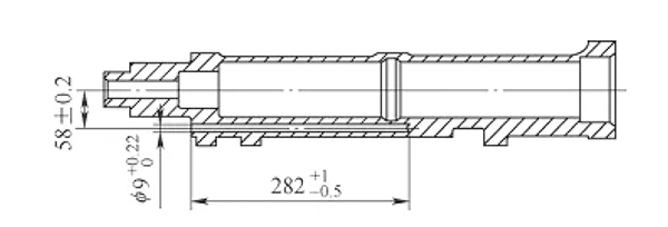
This type of deep hole machining traditionally requires a special machine tool.
For each part, all three groups of tubular holes must be processed separately, requiring three sets of special fixtures. Figure 2 shows the use of these special machine tools and fixtures.
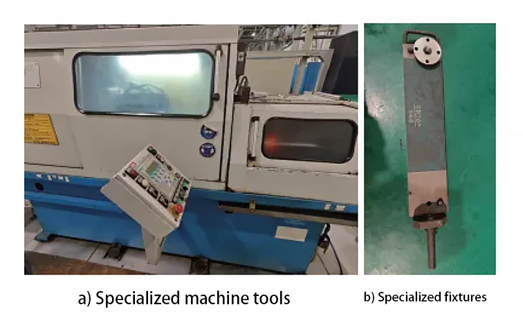
Completion of the part 3 deep hole machining content, a single piece of pure cutting time of 6.58h, cutting time statistics are shown in Table 1.

As can be seen from Table 1, the use of specialized machine tools for processing inefficiency, processing cycle is cumbersome and long.
For batch production of parts, the deep hole machining process has become a bottleneck.
There is an urgent need to improve the processing method and enhance efficiency to meet production requirements.
Problem Analysis
Difficulties in deep hole machining
Deep hole machining mainly has the following difficulties.
(1) large length-to-diameter ratio:
L/D>10 deep hole in the machining process, it is not easy to observe to determine the status of the tool, it is not easy to measure to ensure accuracy.
(2) difficult chip removal:
chips are not easy to discharge, chips through the path of long, easy to block, resulting in tool chipping, it is easy to scratch the machined surface, affecting the surface quality.
(3) Poor heat dissipation:
cutting heat is not easy to spread, the edge is easy to overheat leading to increased tool wear.
Difficult to process materials such as titanium alloy, high temperature alloys, etc. to increase the processing difficulty.
(4) poor rigidity:
too long drill pipe rigidity is poor, easy to deformation, easy to vibration, hole is easy to skew.
Given the challenges in deep hole machining, effective measures can be implemented in several key areas.
These include cooling and lubrication, chip removal, proper guidance, and chip breakage treatment.
High-pressure internal cooling can play the purpose of cooling lubrication and chip discharge, the best choice of oil-based cutting fluid;
The use of guide blocks or improve the accuracy of the guide hole can improve the correctness of the guidance;
The use of self-excited vibration, forced vibration or increase the tool chipbreaker groove method can be fast chip breakage, conducive to the discharge of chips.
Functions of mill-turn machines
The application of advanced high-end CNC machine tools makes the processing content more and more concentrated.
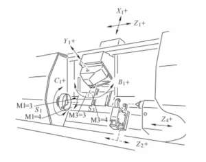
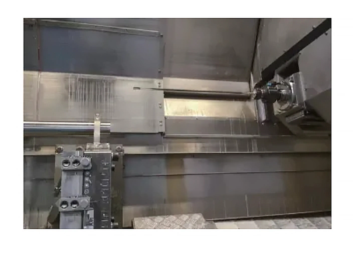
The structure of the mill-turn compound machine tool is shown in Figure 3.
In this figure, M1=3 and M1=4 indicate the forward and reverse rotation of turning spindle S1. Similarly, M3=3 and M3=4 represent the forward and reverse rotation of milling spindle S3, respectively.
The application of mill-turn compound machine tool makes turning, milling, drilling, boring, reaming, tooth machining, deep hole machining and eccentric machining can be concentrated into one process to complete.
This approach makes the machining process more flexible and allows for a higher concentration of processes.
It not only enhances processing efficiency but also reduces the number of clamping operations required throughout machining.
As a result, achieving machining accuracy becomes easier and more reliable.
In particular, it has a deep hole machining capability, in the hydraulic actuator cylinder barrel, piston parts processing, the advantages are particularly obvious.
In this paper, the selection of WFL milling machine tool with 80bar (maximum 350bar, 1bar = 0.1MPa) high-pressure internal cooling function, coupled with its deep boring dovetail unit, can efficiently complete deep hole machining.
Gun drill tool
Deep hole machining tools include deep hole twist drill, gun drill, BTA drill, spray suction drill and DF drill, etc.
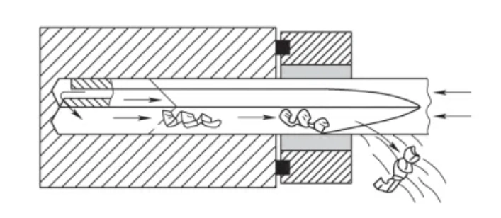
Combined with the machining characteristics of the parts and the size of the holes, the cost of the tools and other factors, the φ9.13mm brazed gun drill is selected for the machining of this part.
The gun drill belongs to the external chip discharge type deep hole drilling, as shown in Figure 4.
It is mainly used to process deep holes with a diameter of 3-30mm, with an L/D ratio of up to 100, the precision of the processed holes is IT8-IT10, and the surface roughness value of the processed surfaces can be up to 0.8-3.2μm.
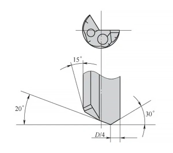
The geometric angle of the gun drill is shown in Figure 5.
The position of the drill tip does not coincide with the center of rotation, and the cutting process is carried out along the inner and outer cutting edges that intersect the drill tip.
The sharpening geometry of a gun drill has a great influence on its chip breakage and life.
Mechanical vibration drilling technology
(1) Principle of vibratory drilling
Vibratory drilling, i.e., drilling with vibration superimposed on the drilling process.
According to the nature of vibration drilling can be divided into self-excited vibration drilling and forced vibration drilling;
According to the vibration device can be divided into ultrasonic vibration, electromagnetic vibration, hydraulic vibration and mechanical vibration.
In this paper, the mechanical vibration drilling technology of French MITIS is selected to solve the problems of low tool life and unstable machining quality in mill-turn composite deep hole machining.
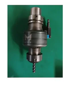
Mechanical vibration toolholder is a device that uses an electric motor to drive an eccentric cam to rotate and generate vibration, as shown in Figure 6.
Mechanical vibration-assisted hole-making technology operates by superimposing a sinusoidal reciprocating motion onto the constant feed movement.
This results in a “micro-vibratory feed,” which creates periodic cutting. As a result, it provides better conditions for heat dissipation and chip breakage.
(2) Vibratory drilling influencing factors
The adjustment of vibration amplitude and cutting parameters has a great influence on chip breakage.
The 3 main parameters of vibratory drilling are: amplitude, frequency and feed.
Amplitude, frequency and feed for the actual drilling angle, the actual chip length and drilling torque have a great impact.
(3) Features and advantages of vibratory drilling
The main features and advantages are as follows.
(1) Improve machining accuracy and surface quality.
The surface of the hole wall with vibration drilling is smooth and uniform, and no chip tumors are generated.
Ordinary cutting process is prone to the existence of chip tumors and involved in cutting, will make the cutting edge radial size increase, resulting in the impact of expansion.
Vibratory drilling destroys the conditions for the existence of chip tumors, which completely eliminates the expansion of the hole diameter caused by chip tumors.
(2) can reduce the drilling force and drilling torque.
Vibratory cutting is a type of pulse cutting with a continuously changing speed and direction of movement.
This process helps the metal transition toward a brittle state while reducing plastic deformation and lowering the coefficient of friction.
As a result, it decreases drilling force and torque while also reducing power consumption.
(3) Cutting temperature is significantly reduced.
Conventional drilling is a semi-closed cutting, drilling a large amount of cutting heat.
The workpiece and drill bit are prone to thermal expansion and deformation due to untimely heat dissipation in the hole, which directly expands the hole diameter.
Vibratory drilling generates lower axial force and torque, allowing for more effective cooling and lubrication.
As a result, the cutting temperature is significantly reduced. This also helps control hole diameter expansion, playing a positive role in maintaining accuracy.
(4) Easy chip processing.
The chip removal in the drilling process directly affects the degree of expansion of the hole diameter.
If the chip removal in the drilling process is not smooth, it will inevitably produce the problem of extrusion and friction of chips involved in cutting, thus making the hole diameter expand.
Vibratory drilling has good chip breaking and chip removal ability, so that the hole diameter expansion caused by chip blockage has been fundamentally solved.
5) Reduce tool wear and extend tool life.
Vibratory cutting reduces drilling resistance and lowers drilling temperature, which, combined with reduced tool wear, helps extend tool life.
A more profound effect is the vibration caused by axial vibratory drilling, which has a rigidizing impact on the vibratory drilling bit.
In the drilling process, the application of pulsed cutting force significantly improves the rigidity of the drill bit.
As a result, the drill bit is less prone to bending and deformation during drilling. This effect effectively prolongs the service life of the tool.
Validation Process
Turn-mill composite deep hole drilling process flow
Drilling deep holes in the mill-turn composite machine tool is different from the traditional process of professional deep hole drilling machine.
The processing of deep holes in professional deep hole drilling machines requires a special fixture, and the drilling sleeve on the special fixture directly ensures the position and accuracy of the hole.
On the other hand, drilling deep holes on a mill-turn machine requires no fixture or drill sleeve.
Due to the gravity of the extended twist drill or gun drill itself, as well as the length-to-diameter ratio of the tool, it is difficult to precisely locate the position of the holes for deep holes.
Therefore, the position and accuracy can only be ensured by first drilling guide holes.
The machining process is shown in Figure 7.

The main process is as follows:
- Drill the pilot hole, the diameter of the pilot hole is larger than the diameter of the gun drill 0.01 ~ 0.02mm (IT7), the minimum depth of 2.5D.
- Low speed (≤ 30r / mi n), low feed and reverse into the pause in the effective depth of the pilot hole from the pilot hole in the 1 ~ 2mm, open the cutting fluid.
- Increase the speed to normal cutting speed, open the feed movement for drilling, the tool can not be retracted, and observe the chip pattern.
- After drilling to the effective depth, the gun drill quickly retreats at the bottom of the hole to the pilot drill, stops rotation and cooling, and quickly retreats to a safe position.
Mechanical vibration drilling machining process
Based on the machining advantages of mechanical vibration drilling, this process uses a mechanical vibration toolholder and gun drill.
By superimposing sinusoidal reciprocating motion onto the straight-line feeding motion of the tool, “micro-vibration feeding” is formed.
The purpose of this technique is to break the chips, which helps improve machining quality and prolong the life of the tool.
(1) Tool clamping
Mechanical vibration drilling technology, the use of French MITIS vibration toolholder clamping gun drill, shown in Figure 8.
Due to its shank structure for the ER32 spring interface, so it must be used to ensure that the internal cooling pressure does not leak pressure.
(2)Processing procedures
Following the machining process of the mill-turn composite gun drill, the pilot hole is drilled first.
Then, the pilot hole is bored, followed by directly processing the effective depth with the gun drill. The program is prepared as follows.
click: CNC code
(3) Machining test parameters
Using mechanical vibration drilling technology, the machining parameters increase the amplitude and frequency.
According to the material characteristics of the parts, heat treatment status, clamping rigidity, and tool material, the chip breakage is verified when machining with different cutting parameters and amplitudes.
This helps control chip shape, improve machining quality, and enhance tool wear resistance.
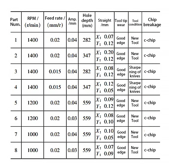
Amplitude and frequency, feed volume for the tool wear and chip breakage, the specific test parameters are shown in Table 2.
(4) Conclusion of machining test
The main conclusions are as follows.
Good chip-breaking effect
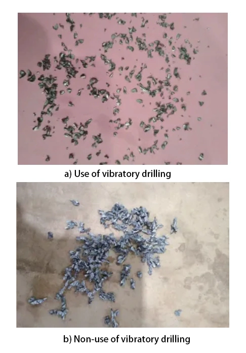
The use of mechanical vibration drilling technology results in good chip breakage, with the chip length generally ranging from 3 to 7mm.
In contrast, without using mechanical vibration drilling technology, the chip length is typically between 18 and 35mm. The chip length for both processing methods is shown in Figure 9.
a) Using vibratory drilling technology
b) Without vibratory drilling technology
Amplitude matches the cutting parameters
The size of the amplitude and the reasonableness of the matching of cutting parameters directly determine the generation of different chip shapes.
In deep hole machining, the criterion for judging chip breakage and smooth chip removal is whether C-shaped chips are generated during the machining process.
The generation of C-shaped chips is also beneficial to the surface roughness of the bore and the tool life.
Impact on tool life
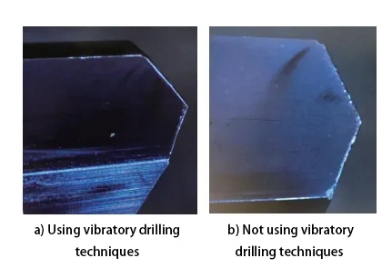
Mechanical vibration drilling also has a great impact on tool life, compared with conventional drilling methods, tool life is significantly improved.
From the cutting statistics, processing the same depth of hole, the use of mechanical vibration drilling technology, tool life compared to the use of side-set shank life increased by more than 30%.
Figure 10 shows a comparison of tool wear under the same machining conditions.
a) With vibratory drilling technology
b) Without vibratory drilling technology
Machining quality and machining efficiency.
After vibratory drilling with mechanical vibration toolholder, the chip breakage and chip removal effect is significantly better than the side-fixed toolholder.
Based on the data from multiple batches of verified parts, the machining quality of the parts is better.
Specifically, the straightness of the holes within a 100mm length offset is within 0.12mm. This eliminates the risk of gun drill breakage in the parts.
From the test cutting, the comprehensive energy efficiency ratio of the tool was measured.
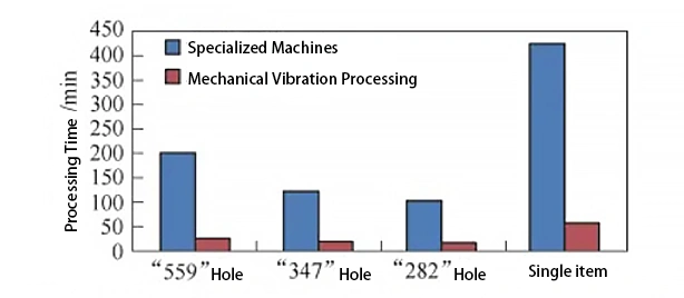
In the mill-turn composite machine tool, when combined with mechanical vibration drilling technology, the efficiency of processing the oil pipe hole is significantly improved.
It is more than 7.5 times higher than in the dedicated machine tool (pure cutting time). This is shown in Figure 11.
Processing on the mill-turn composite machine also saves the stagnation time caused by changing fixtures back and forth, processing efficiency is greatly improved.
Conclusion
In the metal cutting process, the metal material removal rate of hole machining accounts for about 1/3 of the total material removal rate.
Advanced hole machining tools, processes, and methods, both domestically and internationally, aim to improve the efficiency and quality of hole machining.
However, stable and efficient processing of micro-small holes and deep holes remains a challenge we face.
Based on the on-site production process and the problems encountered in hole processing, it is necessary to learn more about the processing tools and introduce new ones.
Additionally, it is important to combine existing theoretical knowledge of hole processing.
This includes verifying machining processes and methods, such as mechanical vibration drilling technology, ultrasonic vibration drilling technology, and other new machining methods.
These are new measures and means to solve the problems of deep hole machining.
These new machining technologies should also be combined with factors such as the machine tool, tool, and workpiece.
Additionally, factors like workpiece material, workpiece clamping rigidity, and machine cooling method should be considered.
More verification and practical testing are needed, along with the collection of processing data and accumulation of experience. This will lay a solid foundation for enhancing our manufacturing capabilities.
FAQ
What is considered a “deep hole” in machining?
Commonly speaking, a deep hole refers to any hole with a length-to-diameter (L/D) ratio greater than 10. Deep hole drilling presents unique challenges due to poor visibility, difficult chip removal, and heat dissipation issues.
Why is deep hole machining difficult?
Deep hole machining is challenging due to:
Long L/D ratio causing poor rigidity and vibration
Difficult chip evacuation leading to tool breakage or surface damage
Poor heat dissipation increasing tool wear
Difficulty in measuring and monitoring cutting conditions inside the workpiece
What tools are commonly used for deep hole drilling?
Tools include twist drills, gun drills, BTA drills, spray suction drills, and DF drills. For holes 3–30 mm in diameter with high depth, gun drills are typically used due to their ability to maintain accuracy and surface finish with L/D ratios up to 100.
How does mechanical vibration drilling improve deep hole machining?
Mechanical vibration drilling adds a sinusoidal vibration to the feed motion, enabling:
Better chip breakage and easier chip removal
Reduced cutting forces and torque
Lower drilling temperature
Improved surface finish and tool life
What are the main advantages of using mill-turn composite machines for deep hole drilling?
Mill-turn machines consolidate turning, milling, and drilling into one setup, offering:
High flexibility and process integration
Fewer clamping operations
Improved positioning accuracy
Enhanced deep hole drilling capabilities with high-pressure internal cooling
Why is a guide hole necessary before deep hole drilling on mill-turn machines?
Since mill-turn machines don’t use special drill sleeves like traditional deep hole machines, a pilot guide hole ensures positional accuracy, supports the tool, and improves chip evacuation during the main drilling operation.
What impact does mechanical vibration drilling have on tool life and hole quality?
Vibratory drilling increases tool life by over 30% compared to conventional methods. It also enhances hole straightness (≤ 0.12 mm offset per 100 mm) and eliminates the risk of chip-related tool breakage, ensuring consistent bore quality.
How does the productivity of vibratory drilling compare to traditional methods?
Using mechanical vibration drilling on mill-turn machines improves cutting efficiency by more than 7.5 times compared to traditional special-purpose drilling machines, especially in high-volume or complex part production.

