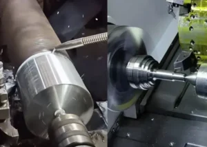
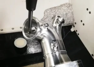
Horizontal CNC boring and milling machines are typically used for machining the internal cavities of cylindrical parts.
The boring bar on this machine extends and retracts axially. It can flexibly enter the interior of the workpiece and machine radial features.
However, special conditions exist for certain machining scenarios.
When machining planes parallel to the workpiece axis, or executing drilling and groove‑milling operations on these planes, the machine needs additional setup.
A right-angle milling head has to be fitted onto the end of the boring bar.
This attachment changes the spatial orientation of the cutting tool.
Although this method has become a standard practice in the field of internal cavity machining, it presents two significant issues:
First, the adoption of a right-angle milling head brings about spatial transformation.
This transformation occurs between the tool axis and the original spindle direction of the machine tool.
It complicates the mapping relationship between the workpiece coordinate system and the machine-tool coordinate system.
Consequently, the difficulty of CNC programming rises substantially.
Meanwhile, the risk of programming errors also increases.
Second, the cutting-tool system needs to stretch into a relatively enclosed cavity during machining.
This condition imposes severe restrictions on the operator’s field of view.
Real-time observation of tool conditions and machining clearance becomes difficult.
As a result, the probability of interference or even tool collision goes up.
These hazards exert direct impacts on machining safety and processing quality.
This paper aims to tackle the above-mentioned problems. It targets the machining of internal cavities on cylindrical workpieces.
The processing equipment adopted is a CNC horizontal boring machine fitted with a right-angle milling head.
A systematic solution is put forward in this work. This solution is built upon digital design and simulation verification.
This study takes NX CAM software platform as the starting point.
It conducts geometric and kinematic modeling for the horizontal CNC boring-milling machine and the right-angle milling head.
Researchers thereby establish an accurate digital twin.
Based on this model, researchers customize a dedicated post-processor to generate machining code accurately and efficiently.
Second, researchers import the established scale model of the machine-tool-cutting-tool system into the VERICUT virtual machining environment to construct a high-fidelity simulation platform.
This platform executes full-process kinematic simulation and collision detection for the generated CNC programs.
Researchers identify and correct potential path errors and interference hazards before physical machining commences.
This paper integrates three core procedures: modeling, customized post-processing, and virtual simulation.
Accordingly, researchers propose a process methodology that can effectively address the challenges posed by complex programming and high collision risks.
These challenges arise from internal-cavity machining with right-angle milling heads.
The objective is to improve reliability, safety, and process controllability of such machining operations.
It further offers a referential technical route for CNC machining of other similar complex-structure components.
Structure of CNC Boring Machines and Right-Angle Milling Heads
CNC horizontal boring and milling machines have become key equipment in industrial production due to their structural characteristics.
The machine mounts the spindle on the side of the worktable, and the spindle head can travel vertically along the column with a long stroke.
The worktable features an open design, facilitating workpiece loading and unloading.
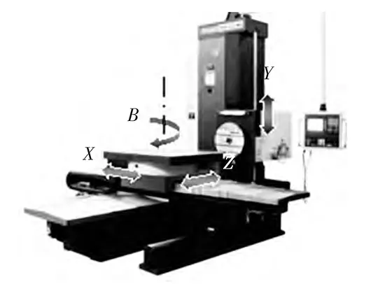
Fitted with rotary‑axis capability (B‑axis), the worktable can position the workpiece in multiple directions and machine several sides in one setup.
This structural design ensures both a wide machining range and flexibility while enhancing production efficiency and precision.
For this reason, CNC horizontal boring and milling machines enjoy extensive application.
Researchers deploy these machines for the machining and manufacturing of complex housings, casings, and large-size molds.
They occupy an irreplaceable and critical position within modern manufacturing.
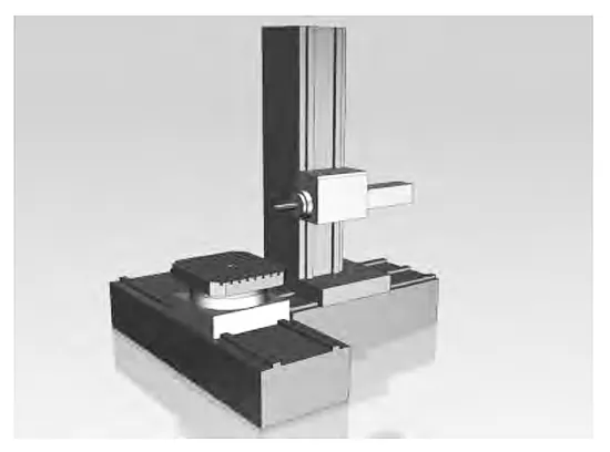
Figure 1 illustrates the basic structure of a CNC horizontal boring and milling machine and the directions of its multiple axes.
The right-angle milling head serves as a key functional accessory for machine tools.
It realizes a 90° spatial transformation between the tool axis and the spindle axis.
In this way, it greatly extends the processing capacities of multi-axis machining centers.
This enables the machining of features—such as side surfaces, internal cavities, and complex curved surfaces—that are difficult to access with a conventional spindle orientation.
However, this structural characteristic also presents a series of machining challenges:
First, the transformation of the tool coordinate system complicates CNC system parameter settings and requires precise calibration of the spatial relationship between the spindle and the attachment.
Second, toolpath planning requires calculations involving multiple coordinate system transformations, significantly increasing the difficulty and workload of CNC programming.
Furthermore, due to the complex spatial orientation of the tool system during machining, operational adjustments and status monitoring are relatively cumbersome.
These problems frequently occur in practical applications. They may readily give rise to programming mistakes and machining collisions.
Such issues can even trigger equipment collision risks. Consequently, they limit further improvements in machining efficiency and safety.
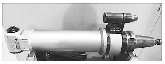
The basic structure of a right-angle milling head is shown in Figure 2.
Hence, researchers need to develop systematic solutions.
They target programming optimization, parameter standardization and process monitoring for right-angle milling head applications.
Developing such solutions has become a vital research direction. It helps elevate the quality and efficiency of complex-part machining.
Construction of Digital Twin Models for Machine Tools and Right-Angle Milling Heads
To achieve highly reliable machining simulations, it is first necessary to construct digital twin geometric models of a CNC horizontal boring and milling machine and its right-angle milling head.
This process begins with precise 1:1 physical surveying of the machine tool’s major components, particularly the various motion axis assemblies.
Based on the survey data, researchers build a scale‑accurate 3D solid model with computer‑aided design (CAD) software.
Afterwards, researchers digitally assemble all component models within the virtual environment.
The assembly strictly follows the real mechanical structure and assembly relationships of the machine tool.
Researchers thus generate a static three-dimensional digital prototype. This prototype fully matches its physical counterpart.
The assembly model of the CNC horizontal boring and milling machine is shown in Figure 3.
This high-fidelity geometric model acts as an accurate spatial framework.
It supports the subsequent integration of kinematic models and drive logic, as well as full-process simulation.
It lays a solid geometric foundation for constructing a complete digital-twin system.
As a critical end-effector in machining systems, the digital twin modeling of right-angle milling heads must achieve a higher level of precision.
During machining, this accessory must work within the workpiece’s confined space.
Operators face restricted physical visibility, a complex motion environment, and substantial interference risks in this area.
To guarantee reliable collision-prediction performance of the digital twin system, researchers take high-accuracy measurements.
Researchers measure key components with sub‑millimeter precision.
These components include connection interfaces, transmission mechanisms, tool-mounting reference points, and external envelopes.
Based on the measured data, researchers build an accurate 1:1 three-dimensional digital model within a CAD environment and carry out virtual assembly following actual assembly relationships.
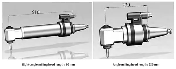
The assembly models for the two sizes of right-angle milling heads are shown in Figure 4.
The construction of this high-fidelity model delivers an accurate geometric description of the end-effector.
It supports the development of a digital twin that reflects real-world machining conditions.
Meanwhile, it forms the core foundation for spatial verification and collision warning within the virtual environment.
Creating a Simulation Process System
After creating scale models of the machine tool and right-angle milling head, you can set up the machine tool model and CNC system in simulation software (Vericut is used in this article).
Once this is complete, you need to verify the correctness of the machine tool’s motion.
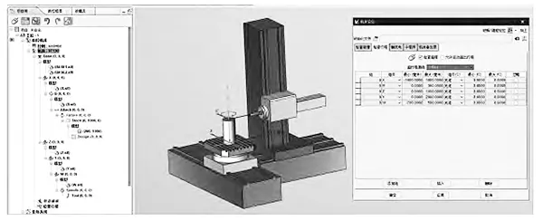
Figure 5 shows how to set up the machine tool structure and configure parameters in the simulation software.
After completing scale-accurate digital modeling of the machine tool body and the right-angle milling head, researchers import these models into the simulation environment to build a complete virtual machining system.
This paper uses VERICUT software as the simulation platform.
First, researchers import and assemble the CAD models of each component following their actual assembly relationships, and configure the corresponding kinematic chains.
At the same time, a matching virtual control system is set up in the software based on the parameters and logic of the actual CNC system.
Once researchers set up the system, they verify the virtual machine tool’s range of motion, direction, and multi-axis interpolation logic via methods including idle runs of each coordinate axis and interpolated-trajectory checks (see Figure 5).
This verification step ensures the accuracy of the digital twin model’s motion behavior and is a necessary prerequisite for the reliable execution of subsequent machining simulations.
Custom Post-Processing for Right-Angle Milling Heads
To accurately generate machining programs compatible with horizontal CNC boring and milling machines and their right-angle milling heads, researchers customize a dedicated post-processor according to the machine tool’s structure and the geometric parameters of its attachments.
Taking the first right-angle milling head configuration shown in Figure 4 as an example, the customization process is as follows:
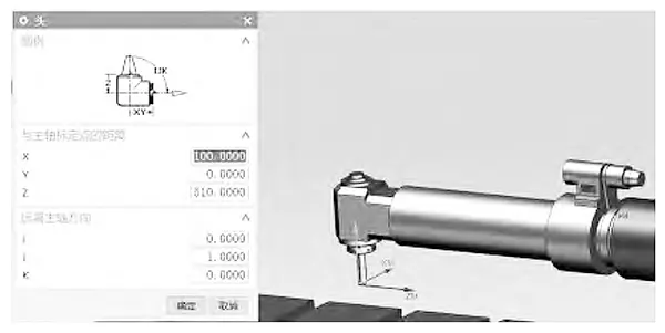
First, within the CAM software environment (NX is used as an example in this paper), establish the corresponding tool orientation and coordinate transformation relationship based on the actual installation direction of the right-angle milling head (set in this paper to be along the machine’s Y-axis).
See Figure 6 for the dimensions and orientation settings of the right-angle milling head.
Within the NX post‑processor builder, researchers configure parameters according to the actual machine tool’s mechanical structure and motion characteristics.
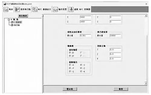
For the four-axis horizontal CNC boring and milling machine described in this article, the fourth rotary axis is set as the B-axis, with its plane of rotation corresponding to the machine tool’s XY plane.
At the same time, researchers define the initial spindle direction as the Z‑axis; this setting matches the machine tool’s actual spindle layout.
The 4th axis and spindle direction configured in the post-processor are shown in Figure 7.
After researchers customize the post‑processor program, they verify its correctness.
In this paper, by programming typical machining operations in the NX CAM environment, we focused on testing the post-processor’s capabilities for tool axis direction conversion and machining plane definition under conditions involving a right-angle milling head.
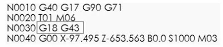
Through program generation and analysis, the verification results show that the customized post-processor can accurately identify changes in tool orientation and correctly output the corresponding commands—under the conditions set in this paper, it successfully outputs the G18 plane (ZX plane) command suitable for side milling.
A screenshot of the beginning of the post-processed NC program is shown in Figure 8.
Machining Simulation Using a Typical Part
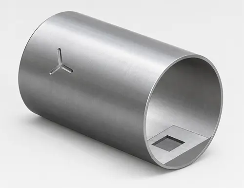
Building on the completion of the machine tool’s digital twin model, control system integration, and the customization and testing of a dedicated post-processor, this paper selects the milling of a square slot in the internal cavity of a cylindrical part—a representative machining feature—as the simulation subject.
A complete programming and simulation verification process based on a right-angle milling head is carried out. The machining features of the typical part are shown in Figure 9.
The simulation process is as follows:
First, in the NX CAM environment, the milling toolpath for the square slot is generated according to the machining process requirements;
Next, the toolpath is converted into NC code executable by the machine tool using the custom post-processor described earlier;
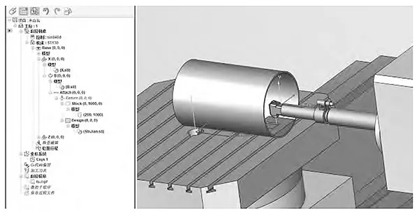
Then, in the VERICUT simulation platform, the generated NC program is loaded into the pre-built digital twin system of the machine tool, and the 3D model of the part to be machined is imported.
The workpiece’s clamping position in the simulation environment is identical to that during actual machining.
By accurately setting the machining coordinate system, it is aligned with the programming coordinate system.
Figure 10 shows the workpiece, program, and coordinate system in the simulation system.
During the simulation process, the system performs real-time calculations and visualizes the relative motion between components such as cutting tools, spindles, milling heads, workpieces, and fixtures, while automatically detecting potential program errors such as collisions, overcutting, and undercutting.
The simulation results effectively identify and pinpoint risk areas, providing a clear basis for program optimization.
Through this simulation verification process, the accuracy and safety of CNC programs can be maximally ensured before physical machining, significantly reducing the risk of machine tool collisions or part scrap caused by programming errors.
It also minimizes the number of test cuts and adjustment time required during actual production, thereby improving machining efficiency and ensuring production safety.
This demonstrates the engineering value of digital twin technology in the machining of complex structures.