
Aluminum alloy wheels serve as both safety components and key aesthetic elements for automobiles.
With the development of China’s automotive industry, vehicle exteriors have become increasingly diverse, leading to a corresponding trend toward greater variety in wheel designs and exterior finishes.
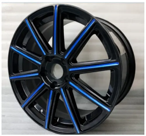
Manufacturing techniques that were previously used primarily in the aftermarket are now gradually being adopted in the original equipment market as well, including multi-color painting, colored clear coats, and surface milling.
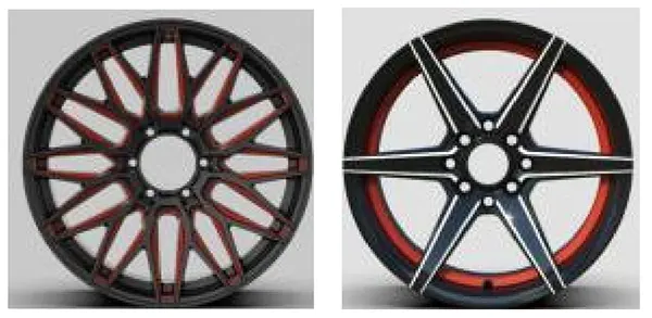
Milling Process Requirements
Milling Process Flow
Cast blank — Heat treatment — Machining — Application of primer and base coat — Milling — Application of clear powder / clear coat.
Appearance Standards for Milling Operations
Milling is classified as a product appearance characteristic rather than an assembly characteristic.
Its core appearance requirements are the surface finish of the milled surfaces and the consistency of the relative positions within the milled areas.
Ensuring product surface finish is primarily controlled through three factors: machine rigidity, cutting tool material and structure, and machining programs.
Existing three-axis machining centers, combined with proven technologies such as diamond milling cutters and program optimization, are capable of meeting surface finish requirements.
The relative positions of the milled areas must remain consistent;
The reference distance between the primary milled areas and the unmachined surfaces should be uniform, and it must be ensured that the positioning center during milling essentially coincides with the theoretical center of the unmachined surface.
Common Machining Methods
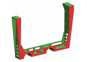
Currently, machining of the blank involves a three-point positioning method for the process wheel flange (Figure 2).
Since the wheel hub is manufactured using an aluminum alloy low-pressure die-casting process, the process wheel flange undergoes significant deformation during mold opening and demolding, and the heat treatment process further increases this deformation.
As a result, there are significant variations in its roundness and flatness.
Furthermore, using the three-point positioning method to forcibly locate the center results in a significant discrepancy between the theoretical center of the blank and the actual machined center after processing.
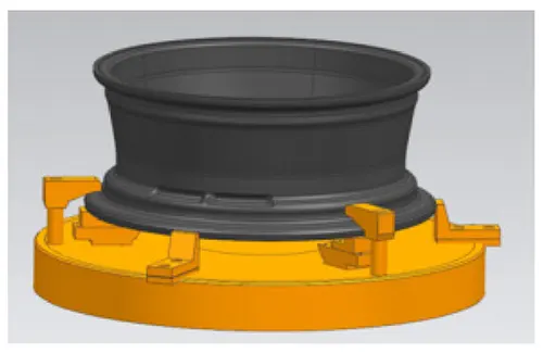
The positioning for milling the product uses a combination of the center hole mandrel to locate the center of the product and the stop pin window:
Because the center hole uses a three-point positioning process with a flanged wheel, there is an offset between the positioning center and the actual center of the blank.
Additionally, due to the unpredictability of blank deformation, the location of the center offset is not fixed.
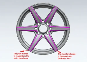
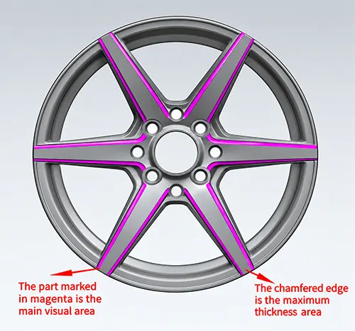
Since the part program is written based on the theoretical center, the width of the milled area (as shown in the magenta region in Figure 3) varies significantly after machining, making it difficult to meet customer requirements.
Optimization of Positioning Fixture Design
Analysis of the product reveals that the primary cause lies in the fact that milling positioning is often based on unmachined areas of the blank, resulting in a significant offset between the milling positioning center and the blank’s theoretical center.
Combined with factors such as significant deformation of the wheel flange during machining, insufficient precision of the positioning fixture, and flash on the positioning surfaces, the center hole created after machining is not suitable as the positioning center for milling.
There are currently various solutions and countermeasures to address the milling offset issue.
One approach involves adding new equipment that captures and analyzes images of the product’s contour to automatically identify the center point.
However, this solution entails high equipment investment costs and is difficult to implement on a widespread basis.
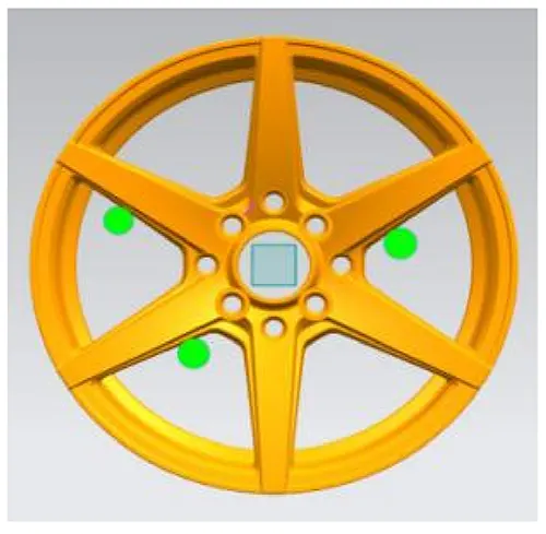
Given the hub’s rotational body structure, the symmetry or uniformity of the spokes, and in conjunction with positioning methods for machined rotational bodies, a three-point positioning system for the wheel spokes was designed based on the principle that three points define a circle.
During the machine setup phase, data points are collected on the hub using a centering rod, and the positions of the three positioning rods are adjusted to ensure that the hub’s coordinate position aligns with the 3D coordinates defined in the program.
Specifically, the value of the Y-axis center point is determined using the correspondence between (X, Y) and (X, -Y), while the value of the X-axis center point is determined using the correspondence between (X, Y) and (-X, Y), thereby establishing the coordinate position of the blank’s center point.
Since the spokes primarily undergo axial deformation during machining, and the deformation pattern is consistent, the differences in the center points of different products after positioning are minimal (as shown in Figure 5).
Therefore, using this method to determine the center point results in minimal positional deviation during milling, meets the surface finish requirements for the milling process, and involves lower costs.
Conclusion
By analyzing the causes of positional deviations in the surface finish of hub milling products, this paper adjusted the positioning method to use the theoretical center of the blank as the reference for machining.
This effectively mitigated surface finish deviations in the milling process and improved both the surface quality and the yield rate of the products.