Parts in CNC machining usually go through several stages. These include design modeling, process planning, programming, setup debugging, simulation verification, tool setting operation, test cutting, quality control, and formal machining.
The operation of the tool is a very important link. It plays a critical role in ensuring the quality of part machining.
Understanding Coordinate Systems in CNC Machining
In CNC machining, the machine tool and the workpiece each involve two coordinate systems. The machine tool manufacturer defines the machine tool coordinate system by a fixed point.
This point serves as the origin of the coordinate system and acts as a reference point for the machine tool. You cannot change it, and people consider it a “fixed point.”
The programmer sets the workpiece coordinate system based on the CNC programming parts design for programming convenience; this coordinate system is variable and acts as a “moving point.”
When the operator mounts the workpiece on the table for processing, they write the program’s coordinate values using the workpiece coordinate system.
This is done to make programming more convenient for the programmer. At this point, however, the CNC system only recognizes the machine coordinate system.
Therefore, it is necessary to establish a connection between the two coordinate systems.
Principle of Tool Setting
An essential method for linking them is through tool setting.
This means using the tool to determine the origin of the workpiece coordinate system within the coordinate values of the machine coordinate system. This process represents the fundamental principle of tool setting.
The following analysis of various methods and applications of tool setting uses the FANUC-0i system of a CNC milling machine tool as an example.
The purpose is to help learners and machining operators establish the work coordinate system accurately, flexibly, and quickly. This system also effectively guides actual production activities.
Tool setting method
CNC milling machines use various methods, and we can divide them into the following three categories based on the different types of tools.
⭑Test cut to the tool method
Usually, cutting tools are used to establish the workpiece coordinate system through the test cut.
⭑Tool-to-Tool method
The main tools are edge finder (mechanical, photoelectric), Z-axis setter, ruler, mandrel, block gauge, etc., through a direct or indirect way to establish the workpiece coordinate system.
⭑Gauge to the tool method
The main percentage or micrometer and other more common gauges to establish the workpiece coordinate system indirectly.
However, regardless of the tool method used, the goal is to directly or indirectly determine the tool position point in the machine coordinate system.
Test cut with the tool method
⭑ Tool setting tool
The tooling method generally processes the first end milling cutter, a preferred flat-bottom end milling cutter, or a round nose cutter.
⭑ Tool setting method
The Trial cutting tool method uses tools that directly cut the workpiece, so that the tool position point and the target workpiece coordinate system origin are indirectly related to the value of establishing the workpiece coordinate system method.
For example, when the blank material measures 100mm × 100mm × 30mm, the programmer establishes the workpiece coordinate system at the center of the blank’s upper surface, usually using the tool setting centering method. The operator follows these main steps.
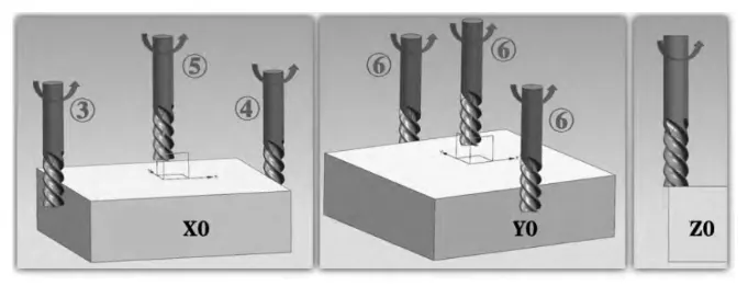
1) Determine X0Y0
1. Select MDI mode, input M03S800 to start the spindle positive rotation; 2. Select handwheel mode, input M03S800 to start the spindle positive rotation.
2. select handwheel mode, multiplier select X100, move table and spindle, quickly position the tool to the safe area on the left side of the workpiece, make sure to keep proper distance from the workpiece;
3. Set the handwheel magnification to X10, slowly approach the tool to the workpiece, let the tool touch the workpiece by listening to the sound, looking at the cut marks, or observing the chips, etc., and set the X-axis value in the relative coordinate system to the zero point at this time.
4. Lift the tool in the positive direction of the Z-axis until it reaches a safe height above the upper surface of the workpiece. Use the same method to let the tool touch the right edge of the workpiece, and record the X-axis value in the relative coordinate system at this time.
5. Back off the tool in the positive Z direction, above the surface of the workpiece, and move the X value of the relative coordinate system to X/2 using the handwheel.
6. Similarly, for Y, the tool stops at Y/2.
7. Switch to the offset coordinate system interface. In G54, enter the X0 measurement, Y0 measurement, and X0Y0 tool setting, which is complete.
2) Determine Z0.
Select the handwheel mode, the spindle is rotating, move the Z-axis just cutting the upper surface of the blank, in the offset coordinate system interface G54 (G54-G59, usually entered in the first coordinate system), Z input Z0 measurement.
The operation process of the test-cutting tool setting method is shown in Figure 1.
⭑ Tool analysis
Fast Tool Setting Method with Trade-offs in Surface Finish and Accuracy
This method is easy to operate, but it may cause cutting marks on the surface of the workpiece, affecting its aesthetics. Tool setting accuracy is not high, so it applies to the blank material cutting process and does not affect the quality of the subsequent parts processing of the case. The tool setting method is fast and efficient.
Rough Tool Setting Using Visual Centering for Improved Efficiency
Because the tool setting method does not control the amount of cutting well, people call it rough tool setting. If the blank size is still sufficient, you can use a ruler to find the center, then move the tool to the center position by observation.
This method can replace the slightly cumbersome centering method, improving efficiency but lowering the accuracy of tool setting.
Efficient One-Side Touch-Off Method for Workpiece Coordinate System Setting
The centering method for tool setting in the XY direction usually requires touching both sides, which is time-consuming.
However, if you already know the blank’s length and width, you only need to touch one side.
You can directly enter the following formula into G54:
X±(LengthorWidth+ToolDiameter)/2X ± (Length or Width + Tool Diameter) / 2X±(LengthorWidth+ToolDiameter)/2
The result can be either a positive or negative number depending on the coordinate system’s orientation.
To determine the rule:
Use the negative value if the test cut point is on the positive side of the workpiece coordinate system.
If it is on the negative side, use the positive value.
Determining Z0 on Uneven Blank Surfaces Using Cross-Milling Method
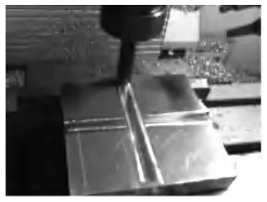
If the upper surface of the blank is usually uneven, the Z0 needs to find the lowest point to prevent the Z value from being too high. If it is too high, the blank’s surface will be directly into the final machining surface, affecting the processing quality.
Theoretically, the operator should mill the uneven surface of the blank flat and then set the cutter. However, this method takes too much time and is inefficient. In actual production, the operator can use the milling cutter to mill in a “cross” pattern to find the lowest point and determine the Z0, as shown in Figure 2.
Tool setting method
⭑ Tooling
The test cut to the tool method applies to rough parts and situations where cutting the workpiece after processing does not affect its quality.
However, if the parts are already processed and their appearance cannot be damaged, you cannot use this method. In such cases, you can choose the tool-to-tool method.
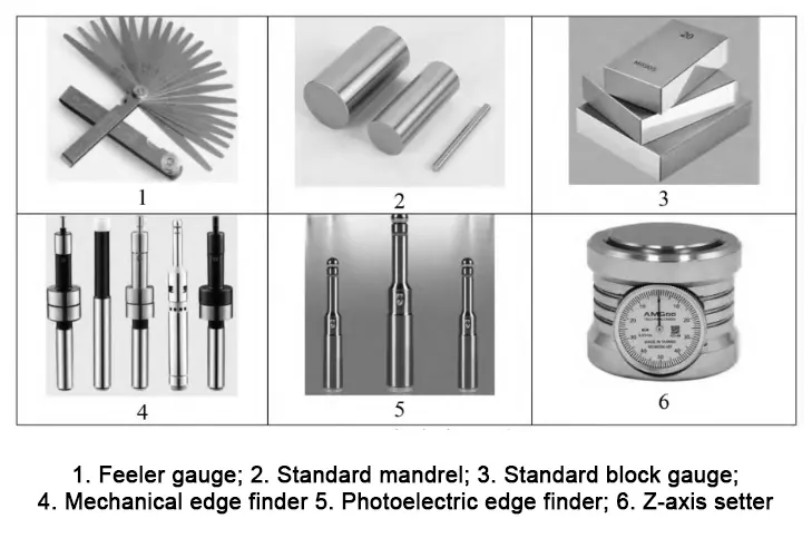
This method uses tooling tools indirectly. Operators usually use edge finders (mechanical and photoelectric types are more common), Z-axis setters, rulers, mandrels, block gauges, and other tools, as shown in Figure 3.
⭑ Tool method
Non-Rotating Tool Setting Method Using Gauge Blocks or Mandrels
Using a tool ruler (or mandrel, block gauge) with the knife is similar to the test cut method, but in this process, the spindle remains stationary and does not rotate.
At the tool and workpiece contact point between the insert ruler (or core rod, block gauge), the ruler can not easily slide until it is clamped.
Points in the tool method should be noted that the tool process does not need to know the plug rule (or mandrel, block gauge) specifications of size, but if it is a one-sided tool method, determining the workpiece coordinate system should pay attention to the plug (or mandrel, block gauge) specifications of the calculation’s size.
In this method of tool setting, the spindle does not rotate, so it does not cause any scratches or damage on the surface of the workpiece.
Although this method does not leave traces on the surface of the workpiece, but its accuracy is not high.
Efficient Tool Setting with Mechanical Edge Finder for XY Zeroing
A mechanical edge finder is an efficient tool-setting method in machining.
It is mainly used to determine the zero position of the X-axis and Y-axis of the workpiece.
The procedure is similar to the test cut method, but the tool is replaced with an edge finder in this process.
This method is widely used in industrial production because it is highly efficient and can ensure accurate tool setting.
However, it should be noted that the spindle speed when using the edge finder is generally not more than 800/rpm; otherwise, the mechanical edge finder will be damaged in the rotation process.
Using a Photoelectric Edge Finder for Accurate XY Zeroing on Conductive Workpieces
the use of photoelectric edge finder to the knife, the workpiece must be a good conductor, and can only determine the X0Y0, in the use of must be cautious, need to let the ball part and the workpiece slight contact, and touch the reference surface has a better surface roughness, to ensure the accuracy of the knife.
Accurate Z0 Determination Using a Z-Axis Setter with Indirect Tool Setting Method
Z-axis setter used to determine the Z0, the first need to calibrate the zero, the spindle does not rotate, to determine the Z0, placed on the upper surface of the workpiece, to be the tool pressed to the Z-axis setter of the upper surface and the dial pointer to 0, at this moment in the off-set coordinate system interface G54, the Z coordinate value is entered into the Z50 (standard height of the setter is generally 50mm) to measure.
This method is an indirect tool setting method, which is more accurate and easier to operate.
⭑ Tool setting analysis
Determining Proper Tool Contact Using Ruler or Gauge Block with Handwheel Control
When using a ruler (or standard mandrel, standard block gauge) on the knife, the appropriate degree of skill is usually measured in the following way: handwheel multiplier X10, turn down a frame that moves down 0.01 mm, the ruler over does not go, turn back a frame that moves up 0.01 mm, the ruler is just right over. We think that this state of affairs is just right contact.
Combining Tool Setting Methods for Accurate XYZ Origin Determination
The tool-to-tool method can be used alone or in combination. For example, the mechanical edge finder or photoelectric edge finder (to determine X0Y0) can be used in combination with the plug ruler, standard mandrel, standard block gauge, and Z direction setter (to determine Z0).
Proper Use of Mechanical Edge Finder: Spindle Speed and Contact Detection Techniques
use mechanical edge finder should pay attention to the spindle speed, generally not more than 800r/min, how to determine the edge finder just contact with the surface of the workpiece, the handwheel multiplier X10, observe the coaxiality of the upper and lower parts, to be the upper and lower parts of the coaxial, continue to move the handwheel for a frame, the upper and lower parts of the exact misalignment, and then back to a frame, that moment the edge finder and the measurement position is just the right contact.
Key Precautions for Accurate Use of Photoelectric Edge Finder on Conductive Workpieces
When using a photoelectric edge finder, attention must be paid to processing the conductive body, ensuring the spindle does not rotate and touches the location of the maximum diameter of the sphere position; otherwise, it will affect the accuracy of the knife.
Gauge tool method
⭑ tool to tool
The method of using the tool for the commonly used percentage table or micrometer is commonly used for cylindrical parts on the knife, but it can also be used for rectangular parts on the knife (slightly troublesome).
Cylindrical parts to the knife, mainly using the “three points to determine a circle” principle to the knife, through the three different positions of the point of measurement, to adjust and ensure that the center of the machine tool spindle and the center of the workpiece coincide.
Rectangular parts tool setting mainly uses the X or Y-axis ends of the circle to adjust the maximum value of the percentage meter, supplemented by the relative coordinates of the zeroing method, which uses two circles on the workpiece symmetry to determine the center of the workpiece.
In CNC machining, a tool-setting method is based on the principle of “three points to determine a circle” in geometry.
This method adjusts and ensures that the center of the machine spindle coincides with the center of the workpiece by measuring three different points.
The procedure is similar to the test cut method, but an edge finder is used instead of a tool to determine these points.
This method is very common in the enterprise because it not only improves the tool’s efficiency but also ensures its accuracy to meet the processing requirements.
⭑ Tool setting method
1) cylindrical parts to determine X0Y0
1. will be equipped with a percent gauge or micrometer magnetic table seat adsorption in the spindle sleeve, see Figure 4.
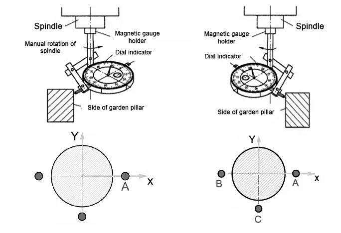
2. move the percentage gauge (or micrometer) pressed on the cylindrical upper surface, manually rotate the spindle to draw a circle, by adjusting the XY axis, so that the center of the tool and the center of the workpiece roughly aligned; 3. by repeatedly fine-tuning the table to determine the X0Y0, the center of the workpiece.
3. Through repeated fine-tuning of the table X and Y-axis position, until the percentage meter pointer in the spindle rotation of one week basically maintained in the same position, and the amount of pointer jump in the permissible tool error range, at this point can be considered as the center of the spindle and the X-axis and the Y-axis of the origin of the reunion.
For example, Figure 4, point A, shows that the meter has a compression value of 0.36mm; 4.
4. manually rotate the spindle so that the dial gauge probe (or micrometer) moves along the circumferential surface of the workpiece to point B. At point B, record the displayed value of the dial gauge, e.g., 0.20mm; 5. slowly move the X-axis of the table so that the center of the table coincides with the origin of the X- and Y-axes.
5. Slowly move the X-axis of the working table so that the pressure gauge at point B is 0.20+(0.36-0.20)/2=0.28mm. If the head is rotated to point A again, the pressure gauge value will be 0.28mm.
6. Turn the spindle when the gauge pointer is at point C, and adjust the gauge pressure gauge value to 0.28mm.
At this point, the center of the spindle can be considered the origin of the X-axis and Y-axis.
2) Determination of rectangular parts X0Y0
1. Attach the magnetic gauge holder with a percentage or micrometer to the spindle sleeve, see Fig. 4.
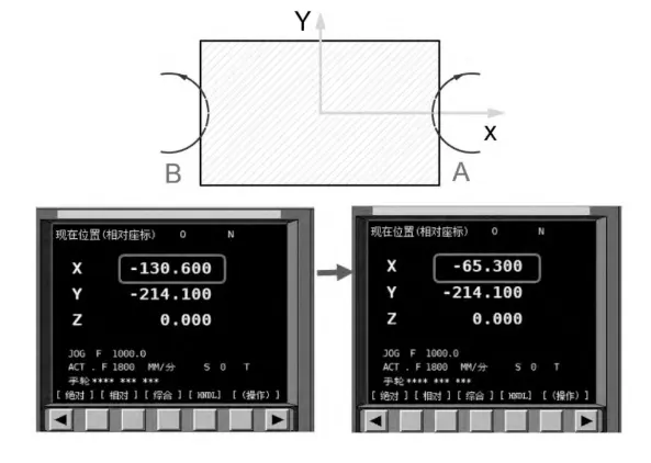
2. Adjust the X, Y, and Z axes with the handwheel so that the contact of the dial gauge (or micrometer) is pressed against one of the sides of the rectangular part in the direction of the X-axis, as shown in Fig. 5, at point A. 3.
3. Manually rotate the spindle, draw a circle of suitable diameter at point A, as shown in Fig. 5, read the maximum reading value of the percentage meter (or micrometer), such as 0.50mm, note down this value, and zero the relative coordinate value at the same time.
4. Lift the Z-axis, use the handwheel to move the dial gauge (or micrometer) to point B at the other end of the workpiece, draw a circle of suitable diameter in the same way, and use the handwheel to adjust to the X-direction position, until the maximum reading value of the dial gauge (or micrometer) is 0.50 mm.
5. Read the relative X-direction coordinates at this point. If the relative X-direction coordinate is -130.60 mm, divide -130.60 mm by 2 to equal -65.30 mm.
Lift the Z-axis and move the X-axis toward the center. The relative coordinate system value is -65.30. At this time, the center of the spindle is located at the origin of the X-axis of the workpiece.
The same method is used to find the center of Y direction. Finally, to switch to the G54 coordinate system interface, input the X0 and Y0 measurements to complete the X0Y0 tool setting.
⭑ Tool analysis
1) Using percentage or micrometer tool settings can achieve a high degree of precision in tool settings. Still, this method’s operation is relatively complex, and the need to repeatedly adjust the pressure gauge value results in relatively low efficiency.
2) In precision machining, such as holes or cylindrical surface finishing, the use of percent or micrometer tool settings can provide high tool setting accuracy.
However, this tool-setting method’s operation process is cumbersome and relatively inefficient, so it is usually not recommended in the roughing stage, considering its machining efficiency and ease of operation.
3) choose a straight line parallel to the X-axis in the tool setting. The closer the line is to the X-axis, the higher the accuracy of the tool setting.
This is because tool settings near the X-axis reduce the deviation caused by machine tool error or improper operation, thus improving machining accuracy.
4) Remember a vital rule when drawing a suitable circle and requesting to adjust the exact value of the pressure gauge.
The gauge holder and the gauge head must not be moved manually. Only movement of the X or Y axis is allowed for adjustment. Otherwise, the tool setting will be completely incorrect.
Conclusion
CNC milling machine tools play a critical role in the quality of parts processing.
Choosing an appropriate and reasonable tool-setting method can protect part quality and greatly enhance production efficiency.
Therefore, users should consider the real production conditions in actual production applications.
They should strictly follow the usage guidelines and precautions for each type of tool setting method.
At the same time, they should choose and apply these methods flexibly based on the specific situation.
FAQ
What is tool setting in CNC machining and why is it important?
Tool setting in CNC machining is the process of establishing the workpiece coordinate system relative to the machine coordinate system. It ensures that the tool knows exactly where to begin cutting, which directly affects part accuracy, surface finish, and production efficiency.
What is the difference between the machine coordinate system and the workpiece coordinate system?
The machine coordinate system is fixed and defined by the machine manufacturer, while the workpiece coordinate system is variable and defined by the programmer for convenience. Tool setting links these two systems to ensure precise machining.
What are the main methods of CNC tool setting?
The three main CNC tool setting methods include:
Test cut to the tool,
Tool-to-tool method (e.g., edge finder, block gauge), and
Gauge-to-tool method (e.g., dial indicator, micrometer).
Each method has specific use cases based on the part, tooling, and required precision.
How does the test cut tool setting method work in CNC milling?
The test cut method involves using a tool (e.g., end mill) to physically touch or cut the workpiece surface. Operators then measure contact points to define the X, Y, and Z origin, ideal for rough parts or initial setups where minor surface damage is acceptable.
When should you use mechanical or photoelectric edge finders in CNC machining?
Mechanical edge finders are great for accurate XY zeroing on most parts, while photoelectric edge finders offer higher sensitivity but require conductive materials and still surfaces. Always limit spindle speed to below 800 RPM when using mechanical types.
How do Z-axis setters improve tool setting accuracy?
Z-axis setters allow operators to indirectly measure and input the Z0 position without rotating the spindle. This prevents damage to finished surfaces and enhances accuracy, making it ideal for finishing stages and complex geometries.
What is the gauge-to-tool method for CNC tool setting?
The gauge-to-tool method uses dial indicators or micrometers to find the center of cylindrical or rectangular workpieces. It’s based on geometric principles like “three points determine a circle” and provides high precision but requires careful adjustment.
How do you determine the origin (X0, Y0, Z0) for cylindrical parts in CNC machining?
Using a dial indicator mounted on the spindle, you manually rotate the spindle while adjusting XY positions until the gauge readings are consistent around the circumference. This aligns the spindle center with the part center to accurately define X0Y0.
What are common errors to avoid during CNC tool setting?
Avoid manually moving the gauge or holder during circular calibration, exceeding spindle speeds when using edge finders, and failing to calibrate setters. Always set relative coordinates carefully to avoid zeroing errors that impact the machining origin.
How do you choose the best tool setting method for your CNC application?
Select the tool setting method based on the part’s stage (rough vs. finish), surface requirements, available tools, and precision needs. For rough setups, use test cuts. For finished parts, use indirect methods like Z-axis setters or edge finders to avoid damage.

