Large-module, multi-start cylindrical worm gears are core components in the drive systems of heavy-duty machine tools and lifting equipment.
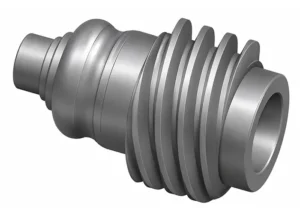
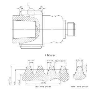
The worm shaft shown in Figure 1 has an axial module of 4 mm, three threads, a helix angle of 20°, a tooth depth of 8.8 mm, and a lead of 37.70 mm.
Traditional machining methods face challenges such as difficulty in sharpening cutting edges, high costs for form cutters, susceptibility to “tool binding,” significant centerline deviation, and low efficiency.
This paper takes this part as the machining subject, analyzes the specific challenges, and proposes targeted solutions to verify the practicality of macro programming technology in the machining of similar parts.
Technical Requirements for Parts
The worm shaft of the reducer shown in Figure 2 is a three-start Archimedean cylindrical worm shaft.
Key Technical Specifications: The axial module (m) of the Archimedean helical worm shaft is 4 mm; the helix angle is 20°;
The lead (L) is 37.70 mm; the pitch line accuracy is ±0.01 mm; the pitch circle diameter is 66.4 mm;
The root circle diameter is 57.2 mm; the surface roughness (Ra) is ≤1.6 μm; and the precision grade is 8f.
Machining Process and Challenges
Machining Process
Taking machining on a FANUC CNC lathe as an example, the process flow is as follows.
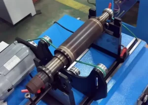
(1) Workpiece Clamping: A self-centering chuck is used to clamp a φ80 mm 45 steel bar blank.
A dial indicator is used to align the outer circular reference, controlling radial runout to ≤0.02 mm, thereby completing the workpiece’s positioning and clamping.
(2) Rough Turning of the Outer Circle: Turn to φ70 mm (leaving a machining allowance for the tooth profile).
(3) Rough Machining of the Tooth Profile: The macro program performs layered cutting, leaving a 0.2 mm finishing allowance.
(4) Finishing of the Tooth Profile: The macro program performs precise pitch line definition followed by precision turning of the tooth profile.
(5) Inspection: Inspection of tooth thickness, pitch line accuracy, and surface roughness.
Machining Challenges
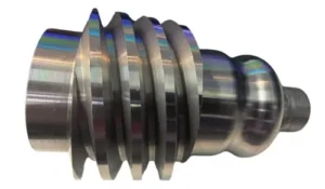
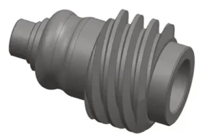
Figure 3 presents the 3D model of the part. We identify the following key challenges in its machining process.
(1) High tooling costs and limited versatility: With a tooth depth of 8.8 mm, manually sharpening tools is difficult and results in poor rigidity; Custom-made form tools are costly.
(2) Risk of “tool chipping” during rough machining: With a tooth depth of 8.8 mm, excessive single-pass cutting allowance can cause tool deformation and surface chipping of the workpiece.
(3) Controlling helical pitch accuracy poses a major challenge. For the three-start worm gear, adjacent helical threads require an axial spacing of 12.566 mm (pitch).
Traditional helical pitch measurement errors tend to exceed the allowable tolerance range of ±0.03 mm.
(4) Conflict between tooth profile accuracy and surface quality: A lead angle of 8°58′ reduces the actual rake angle of the cutting tool, making chip buildup more likely and resulting in poor surface quality.
Analysis of Challenges and Solutions
High Tooling Costs
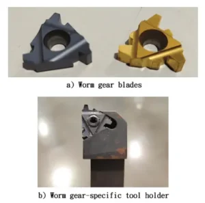
(1) Analysis of Challenges: If specialized cutting tools are custom-made for worm gears (see Figure 4), the cost is relatively high, and since these tools are not used frequently, this leads to waste.
(2) Solution: Use a standard grooving cutter (see Figure 5) with a cutting edge width of 2.5 mm. Simply regrind the left rake angle of the insert according to the helix angle.
Users may replace the insert when not machining worm gears, allowing the tool to function as a grooving cutter.
Rough Machining “Tool Sticking”
(1) Analysis of Challenges: With a tooth depth of 8.8 mm, using a traditional worm-type cutter for rough machining results in multi-edge cutting.
The cutter head lacks sufficient strength, and a single cutting depth exceeding 0.2 mm causes a sharp increase in cutting force (exceeding 300 N), leading to “tool sticking.”
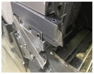
(2) Solution: The tool was replaced with a grooving cutter featuring a 2.5 mm cutting width and an effective length of 10 mm.
With only the primary cutting edge engaged in the cutting process, the tool tip strength was increased by 40%. Programmers adopt a macro program for layered cutting. The macro sets the radial cutting depth to 0.1 mm per layer.
Variable #3 automatically decreases by 0.1 mm after each layer. This method stops multiple cutting edges from engaging the workpiece at the same time. It maintains the cutting force below 150 N.
Inaccurate Line Spacing
(1) Analysis of Challenges: The traditional circumferential line-spacing method is highly susceptible to spindle play.
Operators must keep the axial spacing among the three starts at 12.566 mm in this case. Any play error can easily result in uneven line spacing.
(2) Solution: ① Axial Division Macro: Control the Z-axis offset using variable #1 (division sequence number), where Z = #1 × 12.566 (pitch), to achieve precise positioning of the starting points for the three lines (the three-head worm helical lines).
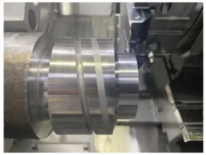
② Multi-pass machining in layers: After machining each helical groove to a depth of 2 mm, switch to machining the other two helical grooves.
Gradually deepen the three helical grooves until machining is complete. The layered machining of the helical grooves is shown in Figure 6.
③ Groove alignment calibration: Before machining, verify the Z-axis offset using a dial indicator, keeping the error within ±0.01 mm.
Tooth Profile Accuracy and Surface Quality
(1) Analysis of Challenges: The helix angle of 8°58′ reduces the actual rake angle on the right side of the tool by 5°, causing the cutting edge to become blunt and making chip buildup more likely.
(2) Solutions: ① Tool Optimization: Increase the rake angle on the right side of the finishing tool to 17° to compensate for the helix angle.
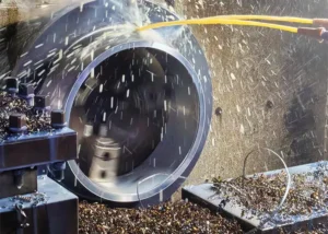
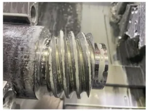
② Cutting Parameter Optimization: Operators raise the finishing speed to 500 r/min and apply high-pressure coolant at 20 L/min to avoid built-up edge formation.
The worm gear machining process is shown in Figure 7.
Machining Macros and Process Validation
The roughing macro (program name O1013) used in this case study is shown in Table 1.
The primary objectives of the finishing macro are to ensure tooth profile accuracy, centerline accuracy, and surface quality, with a cutting depth equal to the allowance reserved during roughing.
Based on the condition of the workpiece after roughing, the finishing macro (program name O1014) is shown in Table 2.
The part inspection results are shown in Table 3.
No. | Program Code | Description |
|---|---|---|
1 |
| Select rough machining tool No. 5 and activate tool offset No. 5. |
2 |
| Start the spindle clockwise at 300 rpm (adjust according to the tool and workpiece material). |
3 |
| Turn on cutting coolant to cool the tool and workpiece and reduce wear. |
4 |
| Rapidly position the tool to a safe location (X86.0 exceeds the tooth tip circle diameter; Z30.0 is outside the front end of the workpiece). |
5 |
| Set variable #1 to 0, representing the first helical groove (indexing sequence values: 0, 1, 2). |
6 |
| Set variable #2 to 2, the indexing counter for the three-start worm (maximum indexing number). |
7 |
| Conditional check: If #1 exceeds #2 (all three helical grooves have been machined), jump to block N10 for tool retraction. |
8 |
| Set variable #3 to 2, representing the initial radial machining allowance (mm). |
9 |
| Set variable #4 to the thread pitch (P = πmₓ = 3.1416 × 4 mm = 12.566 mm). |
10 |
| Set variable #5 to the number of worm starts (z₁ = 3). |
11 |
| Calculate the lead using variable #6 (L = z₁P = 3 × 12.566 mm = 37.70 mm). |
12 |
| Set variable #7 to 80, representing the radial dimension for the first cutting pass (calculated from the reference circle diameter and machining depth). |
13 |
| Conditional check: If #3 is less than 0 (rough machining of the current helical groove is complete), jump to block N6 to switch to the next groove. |
14 |
| Calculate the left-right tool offset based on the 20° tooth profile angle to ensure the cutting path matches the tooth profile. |
15 |
| Rapidly position the Z-axis at the right cutting start point of the helical groove (Z15 is the starting face coordinate; #1 × #4 is the axial indexing offset; #9 is the rightward tool offset). |
16 |
| Rapidly position the X-axis at the cutting start point (2 × #3 represents the radial machining depth in diameter programming, ensuring the tool enters the workpiece). |
17 |
| Perform threading (right tooth flank cutting), feeding to Z−56.0 (the end of the effective workpiece length) with lead variable #6. |
18 |
| Rapidly retract the X-axis to a safe position. |
19 |
| Rapidly position the Z-axis at the left cutting start point of the helical groove (using the negative tool offset #9). |
20 |
| Rapidly position the X-axis at the cutting start point of the helical groove. |
21 |
| Perform threading (left tooth flank cutting) to ensure uniform material removal from both tooth flanks. |
22 |
| Rapidly retract the X-axis. |
23 |
| Return the Z-axis to the workpiece starting face coordinate Z15. |
24 |
| Decrease variable #3 by 0.1 mm (cutting depth per pass: 0.1 mm). |
25 |
| Jump to block N5 and repeat the layered rough machining process. |
26 |
| Increment indexing sequence variable #1 by 1 to switch to the next helical groove. |
27 |
| Jump to block N1 to check whether indexing is complete. |
28 |
| Complete all rough machining operations and rapidly retract the tool to the machine’s safe position. |
29 |
| Pause the program to inspect cutting conditions and tool status (adjust the tool or parameters if necessary). |
Table 1. Rough Machining Program
No. | Program Code | Description |
|---|---|---|
1 |
| Select tool No. 6 and activate tool offset No. 6. |
2 |
| Start spindle clockwise at 500 rpm. The finishing speed is higher than the roughing speed to improve surface quality. |
3 |
| Turn on cutting coolant. |
4 |
| Rapidly position the tool to a safe location. |
5 |
| Set indexing sequence variable #1 to 0. |
6 |
| Set indexing counter variable #2 to 2. |
7 |
| Conditional check: Jump to block N20 when indexing is complete. |
8 |
| Set variable #3 to the full tooth height (h = 2.2mₙ = 8.8 mm). |
9 |
| Set thread pitch variable #4, consistent with rough machining. |
10 |
| Set number of thread starts variable #5, consistent with rough machining. |
11 |
| Calculate lead variable #6, consistent with rough machining. |
12 |
| Set variable #7 to the final diameter (tooth tip circle diameter dₐ = 66.4 mm, determined by design requirements). |
13 |
| Set variable #8 to the left-right tool offset (calculated based on the 2.5 mm tool tip width and tooth groove width to ensure symmetrical tooth profiles). |
14 |
| Conditional check: Jump to block N16 when tooth height machining is complete. |
15 |
| Calculate the tool’s rightward offset. |
16 |
| Position the Z-axis at the right cutting start point (including tool offset #8 to ensure tooth profile accuracy). |
17 |
| Position the X-axis at the cutting start point. |
18 |
| Perform threading (finish machining of the right tooth flank). |
19 |
| Retract the tool along the X-axis. |
20 |
| Position the Z-axis at the left cutting start point. |
21 |
| Position the X-axis at the cutting start point. |
22 |
| Perform threading (finish machining of the left tooth flank). |
23 |
| Retract the tool along the X-axis. |
24 |
| Return the Z-axis to the starting position. |
25 |
| Decrease variable #3 by 0.05 mm (finishing depth of cut is smaller than roughing to ensure surface quality). |
26 |
| Jump to block N15 and repeat the layered finish machining process. |
27 |
| Increment indexing sequence variable #1 by 1. |
28 |
| Jump to block N11 to switch to the next helical groove. |
29 |
| Finish all machining operations and return to a safe position. |
30 |
| End of program. |
Table 2. Finish Machining Program
Inspection Item | Design Requirement | Actual Inspection Result |
|---|---|---|
Indexing Accuracy (mm) | ±0.01 | ±0.008 |
Surface Roughness (Ra, μm) | ≤1.6 | 1.35 |
Tooth Profile Angle (°) | 20 ± 0.5 | 20.05 |
Table 3. Part Inspection Results
Promotion and Application of the Solution
Significance of Promotion
The core value of this case study lies in its “low cost + high adaptability”: there is no need for specialized worm-cutting machine tools;
A standard CNC lathe combined with macro programs can machine large-module, multi-start cylindrical worms. Replacing specialized worm-cutting tools with grooving cutters reduces tooling costs by 60%;
Engineers can directly adopt the layered cutting and axial dividing logic for similar worms with a module of 3–8 mm and 2–4 starts.
Applications
This machining method is particularly suitable for the following types of worms.
1) Operators adjust the macro program according to specific worm parameters for custom worms.
2) Small-batch and single-piece production of worms.
3) Feed drive worms for heavy-duty machine tools, gearbox worms for lifting equipment, and slewing mechanism worms for construction machinery.
Conclusion
This study takes a large-module three-start cylindrical worm gear as the research object and develops a combined machining strategy.
The strategy integrates roughing with grooving cutters, layered cutting based on macro programs, and axial cutting path control.
This approach addresses typical drawbacks of conventional machining, namely tool gouging and out-of-tolerance cutting paths, and achieves efficient, high-precision machining.
The proposed method provides a viable processing solution for small- and medium-sized manufacturers to machine similar workpieces.
It holds promising promotional potential for the production of heavy machinery transmission components.