Imbalance in the rotor of a centrifugal pump is caused by factors such as uneven material microstructure, dimensional deviations in parts, and local asymmetry in the structural shape.
Mass eccentricity causes rotor imbalance. This eccentricity occurs when the rotor’s center of mass deviates from the shaft centerline. Imbalance falls into two categories: static imbalance and dynamic imbalance.
Static imbalance is also called force imbalance. Its center of mass lies parallel to the shaft’s geometric centerline. Dynamic imbalance has a different feature. Its center of mass is neither parallel to the shaft’s geometric centerline nor does it intersect it.
The centrifugal forces resulting from this imbalance act on the rotor bearings, causing vibration, generating noise, and accelerating bearing wear, which severely affects the product’s performance and service life.
Static Balancing and Dynamic Balancing
Static Balancing
Technicians carry out static balancing on a single reference plane of a rotor. Static balancing is also called single-side balancing. Operators control residual unbalance after correction.
This residual unbalance meets the allowable unbalance requirement under static conditions.
Dynamic Balancing
Dynamic balancing involves balancing a rotor simultaneously on two balancing faces. The residual unbalance after balancing ensures that the rotor remains within the specified permissible unbalance limits when in motion.
This process is referred to as dynamic balancing, also known as double-sided balancing.
Selection of Balancing Methods
Principles for Selecting Rotor Balancing Methods
Provided that the rotor’s operational requirements are met, if static balancing alone is sufficient to satisfy these requirements, dynamic balancing may be omitted.
However, other reasonable requirements from the customer must also be taken into account. Most of our company’s rotors undergo dynamic balancing, particularly those for multistage pumps.
Determining Factors
The rotor balancing method should be determined based on the following factors:
(1) The rotor’s geometric shape and structural dimensions, particularly the ratio of the rotor’s diameter D to the distance B between the two reference faces, as well as the rotor’s support spacing, etc.
(2) The operating speed of the rotor.
(3) Relevant standards governing rotor balancing technical requirements, such as GB 3215, API 610, 8th Edition, and ISO 1940.
Conditions for Static Balancing of Rotors
There are three main conditions for performing only static (single-sided) balancing on a rotor:
First, the rotor must have a disc-shaped geometry; second, the support span must be large when the rotor is balanced on a balancing machine;
And third, the end-face runout of the rotor’s balancing surfaces must be very small during rotation.
1. Disc-Shaped Rotors
This is primarily determined by the ratio of the rotor’s diameter D to the distance B between its two balancing faces.
If the part’s D/B ratio is 6 or greater, balancing can be performed in a single plane.
When D/B < 6, this can be used as a criterion to determine whether the rotor is disc-shaped;
However, this is not an absolute rule, as the operating speed of the rotor must also be considered when deciding which type of balancing to perform.
2. Large Support Spacing
Although there are no specific parameter requirements, a ratio of the support span to the distance b between the rotor’s reference surfaces of ≥5 is generally considered sufficient.
3. Axial Runout of the Rotor
This primarily refers to the end-face runout of the reference surfaces when the rotor is rotating.
Since any rotor has undergone precision machining during the balancing process—which ensures the fit tolerance between the rotor bore and the reference surfaces—the end-face runout should be very small.
Conditions for Dynamic Balancing of Rotors
(1) For rotors of single-stage and two-stage pumps operating at speeds of 1,800 rpm or higher, dynamic balancing must be performed provided that D/B is less than 6.
For rotors such as open impellers that cannot be supported at both ends, static balancing alone is sufficient.
Since support at both ends is not possible, this inevitably results in a cantilevered configuration, which is extremely dangerous to balance dynamically on a balancing machine.
(2) For multistage pumps and assembled rotors (rotors with three or more stages), dynamic balancing of the assembled rotor must be performed regardless of the operating speed.
Balancing Accuracy Class
The maximum balancing accuracy is Class G0.4. National standards require that major rotating components, such as impellers, undergo static balancing tests with an accuracy of no less than Class G6.3.
Pump rotors must undergo dynamic balancing tests (some impellers also undergo dynamic balancing), with an accuracy class of no less than G2.5.
API 610 Standard 2.8.4 Balancing
This standard specifies that impellers, balancing drums, and similar major rotating components shall be dynamically balanced to Class G1.0 of ISO 1940 or 7 g·mm, whichever is greater.
The weight of the balancing mandrel shall not exceed the weight of the component being balanced.
Calculation of Unbalance
Permissible unbalance torque for static balancing: M = e × G (g × mm).
Permissible unbalance torque for dynamic balancing: M = 1/2 × e × G (g × mm).
Where: M—torque (g × mm); e—permissible eccentricity (mm) (see attached figure for permissible eccentricity); G—rotor weight (g).
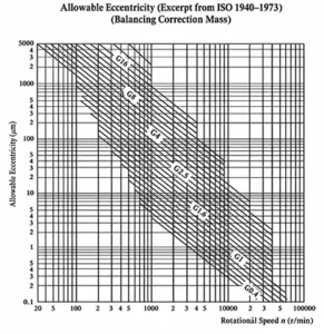
Example: Given that the impeller weighs 2.1 kg, has an outer diameter of Φ135, and the pump rotates at 2940 r/min,
(1) the allowable static unbalanced torque M of the impeller is: M = e × G = 0.02 × 2100 = 42 (g·mm)
Note: Referring to the allowable eccentricity chart, when the pump speed is 2940 r/min, G6.3 indicates that e = 20 μm = 0.02 mm.
Therefore, the allowable unbalanced torque for static balancing of the impeller is:
That is: M = 135/2 × G₁ = 42; thus, G₁ = 0.622 (g)
Hence, the allowable unbalanced mass is less than or equal to 0.622 g (the standard allows 3 g).
(2) Similarly, the allowable unbalanced torque for the impeller’s dynamic balance is:
M = 1/2 × e × G = 0.5 × 0.02 × 2100 = 21 (g·mm)
That is: M = 135/2 × G₂ = 21, so G₂ = 0.311 (g)
Equipment for Measuring Dynamic and Static Balance
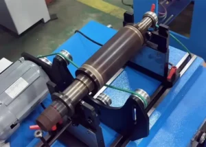
A balancing machine is a device used to measure the magnitude and location of imbalance in rotating objects (rotors).
It is an essential piece of equipment for reducing vibration, improving performance, and enhancing quality.
Typically, rotor balancing involves two steps: measuring and correcting unbalance.
Balancing machines are primarily used to measure unbalance, while unbalance correction is often performed using auxiliary equipment such as lathes, drilling machines, and spot welders, or by hand.
Some balancing machines have the correction device integrated as part of the machine itself.
Support Characteristics
Centrifugal balancers can be classified into soft-support balancers and hard-support balancers based on their support characteristics.
A balancing machine in which the balancing speed exceeds the natural frequency of the rotor-support system is called a soft-support balancing machine.
This type of balancing machine has low support stiffness, and the signal detected by the sensor is proportional to the vibrational displacement of the support.
A balancing machine in which the balancing speed is lower than the natural frequency of the rotor-support system is called a hard-support balancing machine.
This type of balancing machine has high support stiffness, and the signal detected by the sensor is proportional to the vibrational force of the support.
Performance
The primary performance of a balancing machine is represented by two comprehensive indicators: the minimum achievable residual unbalance and the unbalance reduction rate.
The former refers to the minimum residual unbalance that the balancing machine can achieve for a rotor and serves as an indicator of the machine’s maximum balancing capability;
The latter is the ratio of the unbalance reduced after a single correction to the initial unbalance, and it serves as an indicator of balancing efficiency, typically expressed as a percentage.
Due to the widespread use of flexible rotors in modern machinery, flexible rotor balancing machines have been developed.
This type of balancing machine must be capable of stepless speed regulation within the rotor’s operating speed range;
In addition to measuring the vibration or vibrational force of the bearings, it can also measure the flexural deformation of the rotor.
Some flexible rotor balancing machines are installed in vacuum chambers to accommodate the balancing of steam turbine rotors;
They are equipped with auxiliary equipment such as a vacuum system, a lubrication system, a lubricating oil degassing system, and a computer system for data processing.
Conclusion
Rotating components such as pump rotors, motor rotors, and turbine rotors must all undergo balancing during the manufacturing process to ensure smooth and normal operation.
Operators use measurement data from a balancing machine to correct rotor unbalance.
They optimize the mass distribution around the rotation axis. This adjustment cuts vibration during rotation.
It also lowers vibrational loads applied to bearings. Operators keep these vibration values within allowable limits.
The measure guarantees stable operation of the finished products.