As the company has grown, its product range has expanded, and the requirements for machining precision have become increasingly stringent.
In the past, dimensional and geometric tolerances for large structural components were generally set at ±0.05 mm;
In recent years, however, the basic dimensional tolerance requirement for structural components undertaken by the company has been ±0.03 mm.
To address the machining of thin-walled aluminum alloy parts with low rigidity, improvements have been made in three areas—process planning, clamping methods, and toolpath planning—which effectively control part deformation.
Machining Challenges
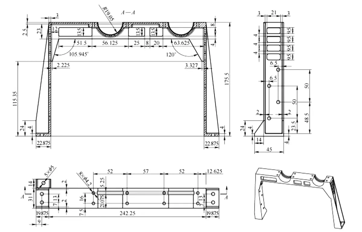
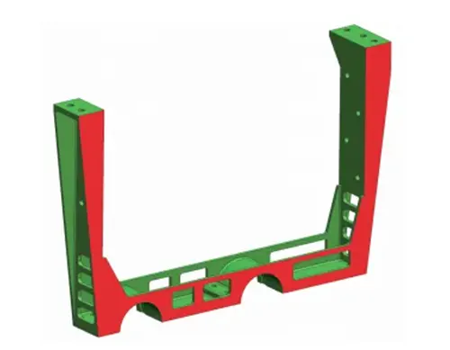
The thin-walled aluminum alloy part with low rigidity, shown in Figure 1, is made of 7075 aluminum alloy.
The part measures 282 mm in length, 175.5 mm in width, and has a main body thickness of 31 mm.
After machining and forming, the thinnest wall thickness of the part is 2 mm.
The dimensional tolerance for the distance between the two support legs is ±0.03 mm, and the dimensional tolerance for the mounting surface is ±0.03 mm.
Since the material removal rate exceeds 95% and the area between the two support legs is open, this part is a typical low-rigidity thin-walled component.
The key challenge in machining this part lies in controlling deformation of the two support legs.
According to the tolerance requirements, post-machining deformation must be controlled within 0.05 mm.
If the part deforms, all critical dimensions will exceed tolerances, resulting in the part being scrapped.
Process Analysis
The following analysis addresses the challenges associated with machining.
Process Requirements
Based on previous machining experience, the part undergoes three stages of aging treatment.
The first stage involves uniform rough machining, leaving a 3 mm allowance before aging treatment;
The second stage involves uniform rough machining, leaving a 2 mm allowance before aging treatment;
And the third stage involves uniform rough machining, leaving a 1 mm allowance before aging treatment.
Clamping Method
Based on the part’s structural configuration, the following points must be observed:
① During clamping, the part must not be subjected to external forces.
If clamped using external forces, the part will experience springback deformation once the clamping force is released.
② The clamping contact area must be sufficiently large, particularly at the two support legs.
③ Part clamping must adhere to the principle of a unified reference.
Since all surfaces of the part require machining, which necessitates multiple clamping operations, a unified reference must be established.
Toolpath Planning
A well-designed toolpath can significantly reduce the cutting forces exerted on the part during machining.
Process Improvement Measures
Relieving Internal Stresses
During machining, perform three aging treatments in accordance with specific process requirements to fully relieve internal stresses in the part material.
It is important to note that during the second and third roughing operations, the clamping forces on the part must be controlled;
Use a torque wrench to ensure that the clamping force remains below 15 N.
Innovative Clamping Method
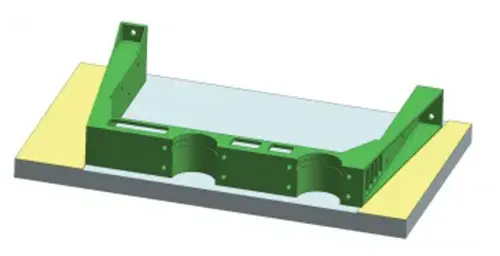
During finishing operations, use the red surface shown in Figure 2 as the mounting and positioning surface, and secure the workpiece to the fixture plate with 302 adhesive (see Figure 3).
Based on the angles of the part’s contour, set up V-shaped stop blocks on the fixture plate with the same angles and a height of 1 mm (see the yellow sections in Figure 3).
This effectively restricts the workpiece’s five degrees of freedom, ensuring accurate positioning.
During clamping, ensure that the left and right slanted edges of the workpiece are in close contact with the V-shaped stop on the fixture.
Then, apply 302 adhesive to the contact edges between the workpiece and the fixture to secure it.
Once clamping is complete, machine the part’s external dimensions and square cavity to meet design requirements.
Flip the part over and clamp it in the same manner to machine the opposite side, ensuring the total thickness dimension is maintained.
With this, all six sides of the workpiece have been machined, leaving only the internal cavity unmachined.
At this point, a third clamping operation is required. To ensure sufficient clamping strength, a fixture must be designed to maximize the clamping contact area.
Fabrication of Specialized Fixtures
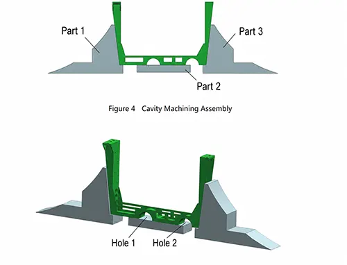
Due to the large dimensions of the part, fabricating the internal cavity machining fixture as a single-piece unit would result in significant waste of fixture material; therefore, a modular design was considered.
The internal cavity machining fixture, as shown in Figure 4, consists of fixture components 1, 2, and 3.
Since the part’s external dimensions have already been machined to specification, the fixture is machined with each side expanded by 0.06–0.10 mm relative to the part’s outer contour to ensure the part fits smoothly and that both sides and the bottom surface are in close contact with the fixture surfaces.
After placing the part into the fixture, first secure it with an appropriately weighted object, then bond it in place using 302 adhesive.
As shown in Figure 5, Holes 1 and 2 are the areas of the part most prone to deformation, so additional reinforcement is required at these locations.
Once the 302 adhesive has cured, diamond putty or fireproof putty can be packed into Holes 1 and 2.
If these materials are unavailable, a wet towel rolled up after being soaked in water can be inserted instead.
This not only increases the part’s strength but also prevents resonance during the machining process.
Optimizing Machining Paths
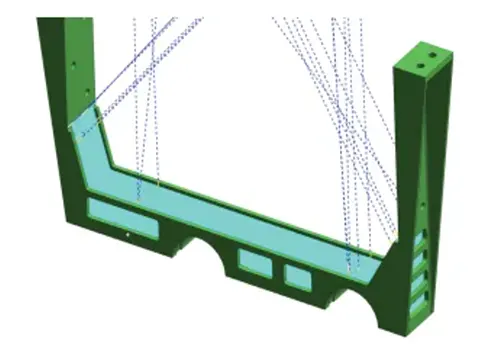
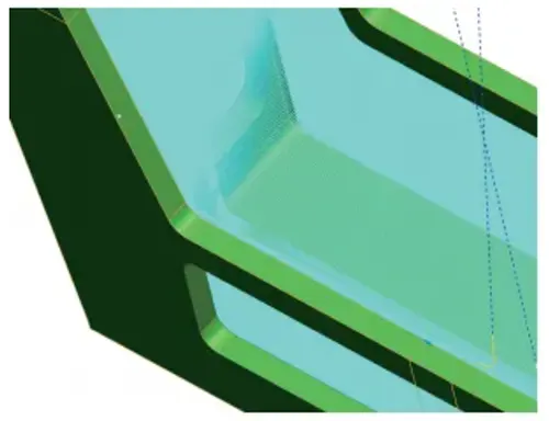
The machining path for the entire internal cavity is shown in Figure 6, and a close-up of the machining path for the internal cavity is shown in Figure 7.
First, the toolpath should follow a reciprocating motion along the length of the part, avoiding lateral movement to ensure that the cutting force remains in a single direction throughout the process.
Second, the number of corners in the toolpath should be minimized to prevent sudden increases in cutting force during machining, thereby ensuring uniform cutting force throughout the entire process.
When machining with a five-axis CNC machine tool, reducing the tool overhang effectively enhances tool strength and machining efficiency, ensuring high-quality results.
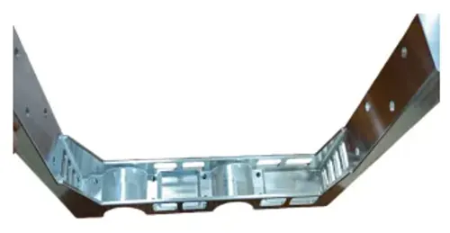
After implementing the above improvements, the machining results for the parts are shown in Figure 8.
A full-dimension inspection using a coordinate measuring machine was performed on this batch of parts;
All dimensions met specifications, and part deformation was kept within 0.03 mm.
Conclusion
As spacecraft design trends toward lighter weight and greater integration, there is an increasing number of thin-walled and low-rigidity parts.
Consequently, controlling machining deformation has become particularly important.
This paper presents a comprehensive analysis of the machining process for low-rigidity, thin-walled aluminum alloy parts.
Through comprehensive optimization of the machining strategy, clamping methods, and toolpath planning, a split-type support fixture was designed and fabricated.
This effectively controlled machining deformation and improved both the quality and efficiency of part production.