
Tolerances and fits constitute foundational theoretical knowledge in mechanical engineering.
The core origin of these systematic concepts lies in the requirement for part interchangeability within machinery manufacturing.
Machine‑tool, cutting‑tool and measurement‑equipment constraints prevent engineers from obtaining perfectly precise dimensions in mechanical processing.
Engineers establish tolerance standards to confine machining errors within a reasonable range, whereas fit rules define assembly coordination for mating holes and shafts.
This article first explains the origin and practical value of interchangeability, then systematically sorts out core terminology related to dimensional tolerances and fits, including tolerance zones, standard tolerance grades, basic deviations, fit classification and two fit reference systems.
It further elaborates on shape tolerances and positional tolerances, forming a complete framework for geometric tolerance knowledge for mechanical design and manufacturing practitioners.
Why do the Concepts of Tolerances and Fits Exist?
This all starts with interchangeability! What is interchangeability?
In the machinery and instrument manufacturing industries, engineers define the interchangeability of parts and components as the ability to select any single part from a batch of parts or components with the same specifications.
Workers can install the selected part directly onto a machine without sorting or additional adjustments, such as fitting by a machinist.
This process allows the machine to achieve the specified performance requirements.
To ensure the interchangeability of parts in mechanical manufacturing, the dimensions of produced parts must fall within permissible tolerance limits.
This necessitates establishing a unified standard for a part’s form, dimensions, precision, and performance.
Engineers also reasonably classify identical‑type products by size to reduce the number of product series; this practice represents product standardization.
Practical Value of Interchangeability in Product Usage
From a usage perspective—such as parts for commonly used bicycles and watches, or parts for various pieces of equipment used in production—when these items break down, repair personnel can quickly replace them with parts of the same specifications to restore the functionality of bicycles, watches, and equipment.
In certain situations, the role played by interchangeability is difficult to quantify in terms of value.
For example, on the battlefield, where it is essential to immediately troubleshoot and repair weapons and equipment to continue combat, the interchangeability of key components is absolutely necessary.
Manufacturing‑oriented Advantages of Interchangeability
From a manufacturing perspective, interchangeability is a powerful means of improving production standards and promoting efficient production.
During assembly, engineers eliminate auxiliary machining and fitting operations.
This reduces assembly‑workers’ labor intensity, shortens assembly cycles, enables line‑based manual assembly and even automated assembly, and therefore greatly boosts production efficiency.
During machining, because engineers define tolerance values, they can fabricate different parts for the same machine tool in parallel.
Specialized factories also mass‑produce standard components independently.
This allows for the use of high-efficiency specialized equipment and even computer-aided machining.
Accordingly, manufacturers boost both output and product quality while substantially cutting production costs.
Design‑related Benefits Brought by Interchangeability
From a design perspective, applying the principle of interchangeability to the design and production of standard parts and components simplifies tasks such as drafting and calculations, shortens the design cycle, and facilitates the use of computer-aided design (CAD).
Concepts of Tolerances and Fits
Terminology Related to Tolerances
During the machining process, it is impossible to machine a part to absolute dimensional accuracy due to factors such as machine tool precision, tool wear, and measurement errors.
To guarantee part interchangeability, engineers confine dimensional machining errors within a definite range and define allowable dimensional variations.
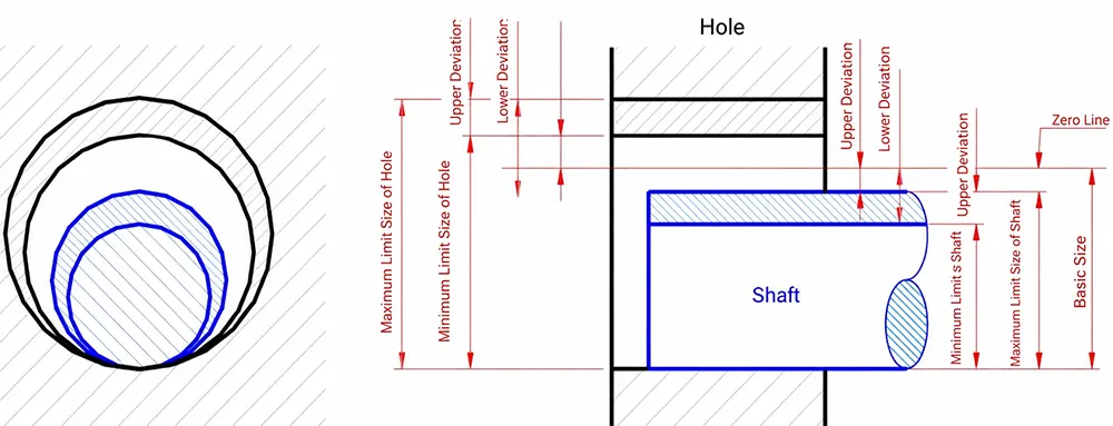
1. Basic Dimension
A dimension determined during the design process based on the part’s strength and structural requirements.
2. Actual Dimension
A dimension obtained through measurement.
3. Limit Dimensions
The two boundary values within which dimensional variation is permitted.
These are determined based on the basic dimension.
Engineers term the larger boundary value the maximum limit dimension and the smaller one the minimum limit dimension.
4. Dimensional Tolerance (abbreviated as tolerance)
The algebraic difference obtained by subtracting the basic dimension from a given dimension. Dimensional tolerances include:
Upper tolerance = Maximum limit dimension – Basic dimension
Lower tolerance = Minimum limit dimension – Basic dimension
The upper and lower tolerances are collectively referred to as limit tolerances; they can be positive, negative, or zero.
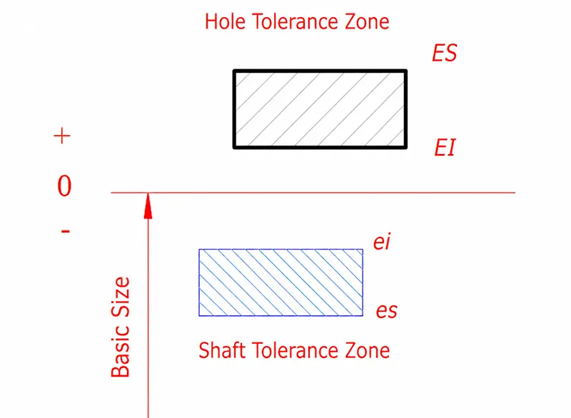
National standards specify that the code for the upper deviation of a hole is ES, and the code for the lower deviation is EI;
The code for the upper deviation of a shaft is es, and the code for the lower deviation is ei.
5. Dimensional Tolerance (abbreviated as tolerance)
The allowable range of variation in dimensions.
Dimensional tolerance = Maximum limit dimension – Minimum limit dimension = Upper deviation – Lower deviation
Since the maximum limit dimension is always greater than the minimum limit dimension—that is, the upper deviation is always greater than the lower deviation—the dimensional tolerance is always a positive value.
6. Zero Line, Tolerance Zone, and Tolerance Zone Diagram
The zero line is a reference line used in a tolerance zone diagram to define deviations; that is, the zero-deviation line.
Typically, the zero line represents the basic dimension.
The symbols “0,” “+,” and “−” are marked at the left end of the zero line; deviations above the zero line are positive, while those below are negative.
Two straight lines representing the upper and lower deviations bound the tolerance zone.
The width and position of the tolerance zone are the two elements that define it.
7. Standard Tolerances and Standard Tolerance Grades
A national standard lists any standard tolerance that determines the size of the tolerance zone.
A standard tolerance grade is a classification that determines the degree of dimensional accuracy.
Engineers classify standard tolerances into twenty grades: IT01, IT0, and IT1 through IT18.
“IT” denotes the standard tolerance, and the Arabic numerals indicate the standard tolerance grade, with IT01 being the highest grade and IT18 the lowest, in descending order.
For a given basic dimension, the higher the standard tolerance grade, the smaller the standard tolerance value, and the higher the dimensional accuracy.
8. Basic Deviation
Used to determine whether the tolerance zone is above or below the zero line.
Generally, it refers to the deviation closest to the zero line. When the tolerance zone is above the zero line, the basic deviation is the lower deviation;
When the tolerance zone is below the zero line, the basic deviation is the upper deviation.
Based on practical needs, national standards specify 28 different basic deviations for holes and shafts, respectively, as shown in the figure below.
The values of the basic deviations for holes and shafts can be found in the relevant tables.
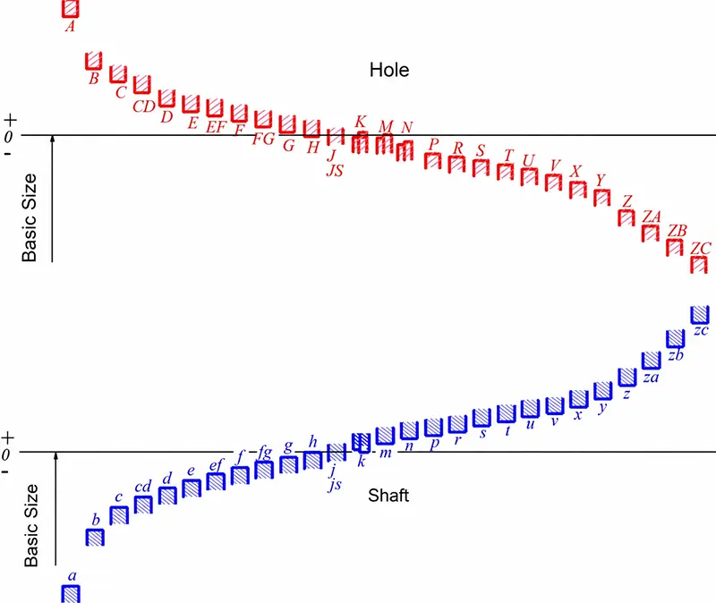
As shown in the figure above:
1) Engineers use Latin letters for basic‑deviation codes: uppercase letters designate hole‑related basic‑deviation codes, while lowercase letters denote shaft‑related basic‑deviation codes.
Because engineers employ the basic‑deviation value in diagrams only to indicate tolerance‑zone magnitude, they draw one end of the tolerance zone as open‑ended.
2) For the basic deviation, A through H represent the lower deviation, and J through ZC represent the upper deviation;
For JS, the upper and lower deviations are +IT/2 and -IT/2, respectively.
3) For the basic deviation of the shaft, a through h represent the upper deviation, and j through zc represent the lower deviation;
For JS, the upper and lower deviations are +IT/2T and -IT/2, respectively.
Engineers compute the remaining deviation for holes and shafts using the basic deviation and standard tolerance value.
Terminology Related to Fits
In machine assembly, the relationship between the tolerance zones of a hole and a shaft that join together and share the same basic dimensions defines a fit.
Because the actual dimensions of the hole and the shaft differ, a “clearance” or “interference” may result after assembly.
In a hole-and-shaft fit, if the algebraic difference obtained by subtracting the shaft’s dimension from the hole’s dimension is positive, it is a clearance; if it is negative, it is an interference.
1. Types of Fits
Engineers categorize fits into three groups according to clearance‑or‑interference conditions.
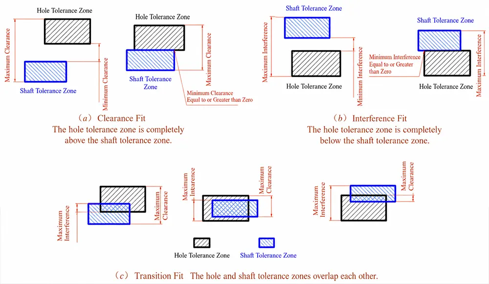
1) Clearance Fit
The tolerance zone of the bore lies above that of the shaft;
Any pair of bore and shaft selected will result in a fit with clearance (including a minimum clearance of zero), as shown in Figure a above.
2) Interference Fit
The tolerance zone of the hole lies below that of the shaft;
Any pair of holes and shafts selected from these will result in a fit with interference (including a minimum clearance of zero), as shown in Figure b above.
3) Transitional Fit
The tolerance zones of the hole and shaft overlap. When engineers select arbitrary hole‑shaft pairs for assembly matching, they may obtain either a clearance fit or an interference fit, as illustrated in Figure c above.
2. Reference Systems for Fitting
National standards specify two reference systems, as shown in the figure below.
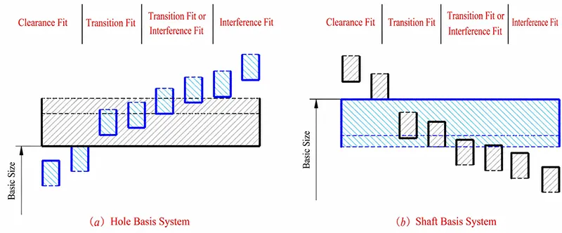
1) Reference Hole System
A system of fits in which the tolerance zone of a hole with a fixed basic deviation is combined with the tolerance zone of a shaft with a basic deviation, as shown in Figure a.
In other words, for fits with the same basic dimension, the position of the hole’s tolerance zone is fixed, and different fits are obtained by varying the position of the shaft’s tolerance zone.
Engineers designate the hole within the base‑hole system as the reference hole;
National standards specify that the lower deviation of the reference hole is zero, and “H” is the basic deviation symbol for the reference hole.
2) Shaft-Based System
Engineers establish a system whereby a shaft with fixed basic‑deviation tolerance zone pairs with holes of varying basic‑deviation tolerance zones to produce diverse fits, as illustrated in Figure b.
In other words, for fits sharing an identical basic size, engineers keep the shaft‑tolerance‑zone position fixed and generate different fits by adjusting the position of the hole’s tolerance zone.
Engineers define the hole within the base‑shaft system as the reference sleeve.
National standards specify that the lower deviation of the reference shaft is zero, and “h” is the basic deviation symbol for the reference shaft.
As can be seen from the basic deviation series chart:
Within the base‑hole system, engineers mate the reference hole H with shafts. They employ codes a‑h (eleven total) for clearance fits, and j‑n (five total) mainly for transition fits.
(n, p, and r may be either transitional or interference fits); and p–zc (12 types in total) are primarily used for interference fits.
In the reference shaft system, the reference shaft h is mated with a bore; A–H (11 types in total) are used for clearance fits;
J–N (5 types in total) are primarily used for transitional fits; (N, P, and R may be either transitional or interference fits);
P–ZC (12 types in total) are primarily used for interference fits.
Shape Tolerances
Shape tolerance refers to the total allowable variation in the shape of a single actual feature.
Shape tolerances are expressed as shape tolerance zones. A shape tolerance zone comprises four elements: shape, direction, position, and magnitude.
There are six types of shape tolerances: straightness, flatness, roundness, cylindricity, line profile, and surface profile.
Straightness
Straightness indicates the degree to which the actual shape of a straight line feature on a part conforms to an ideal straight line.
It is commonly referred to as the degree of straightness.
The straightness tolerance is the maximum allowable deviation of the actual line from the ideal straight line.
In other words, it is the range of variation specified in the drawing to limit machining errors on the actual line.
Flatness
Flatness indicates the degree to which the actual shape of a part’s planar features conforms to an ideal plane.
It is commonly referred to as the degree of flatness. The flatness tolerance is the maximum allowable deviation of the actual surface from the ideal plane.
It is the permissible range specified on the drawing to limit machining errors on the actual surface.
Roundness
Roundness describes the actual shape of a part’s circular features and their equidistance from the center.
It is commonly referred to as the degree of circularity. The roundness tolerance is the maximum allowable deviation of the actual circle from the ideal circle within the same cross-section.
It is the range of variation specified on the drawing to limit machining errors on the actual circle.
Cylindricity
Cylindricity refers to the degree to which points on the outer contour of a cylindrical surface on a part maintain an equal distance from its axis.
The cylindricity tolerance is the maximum allowable deviation of the actual cylindrical surface from the ideal cylindrical surface.
In other words, it is the permissible range of variation specified on the drawing to limit machining errors on the actual cylindrical surface.
Line Profile
Line profile refers to the condition in which a curve of any shape on a given plane of a part maintains its ideal shape.
The line profile tolerance refers to the allowable variation of the actual contour line of a non-circular curve.
In other words, it is the range of variation specified on the drawing to limit machining errors in the actual curve.
Surface Profile
Surface profile refers to the degree to which a surface of any shape on a part maintains its ideal form.
Surface profile tolerance refers to the allowable variation of the actual contour line of a non-circular surface relative to the ideal contour surface.
In other words, it is a value specified on the drawing to limit the permissible range of machining errors for the actual surface.
Positional Tolerances
Positional tolerances refer to the total allowable variation in the position of an actual feature relative to a reference.
Orientational Tolerances
Orientational tolerances refer to the total allowable variation in the orientation of an actual feature relative to a reference.
This category includes three types of tolerances: parallelism, perpendicularity, and inclination.
Positioning Tolerance
Positioning tolerance refers to the total allowable variation in the position of an actual element relative to a reference.
This category of tolerance includes three items: coaxiality, symmetry, and positional accuracy.
Runout Tolerance
Runout tolerance is a tolerance item defined based on a specific inspection method.
Runout tolerance can be divided into circular runout and total runout.
Conclusion
In summary, tolerance and fit systems are built around the core demand of part interchangeability, serving the whole chain of mechanical product design, production, assembly and maintenance.
Dimensional tolerances define the permissible dimensional variation of machined components, and standard tolerance grades and basic deviation codes provide unified industry criteria for dimension control.
Clearance fits, transition fits and interference fits, together with hole-base and shaft-base reference systems, guide engineers to select proper assembly coordination modes.
Beyond dimensional requirements, shape tolerances and positional tolerances further constrain geometric errors of part features.
Mastering these theories enables designers to set reasonable accuracy requirements, helps factories arrange machining processes properly, guarantees smooth assembly of mechanical products, reduces production costs, and realizes efficient batch manufacturing of interchangeable parts.