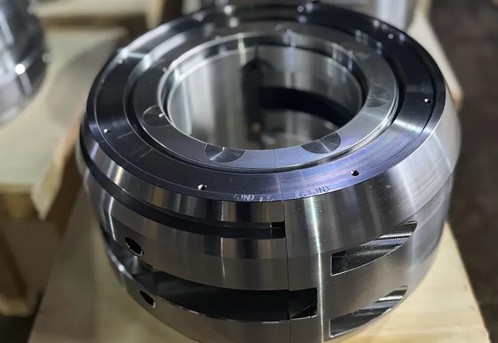
During CNC machine tool processing, deformation errors are prone to occur at the corner transition positions of workpieces due to various factors such as machine tool structure, cutting forces, and temperature changes.
These deformation errors not only reduce the processing accuracy of workpieces but also affect their assembly and performance.
Fields with high precision requirements include aerospace and automotive manufacturing. In these fields, corner transition deformation errors may lead to scrap parts.
These errors may also require additional processing and corrections. As a result, they increase manufacturing costs and time.
Manufacturers need to compensate for deformation errors in the CNC machining process.
This compensation improves the precision of workpiece processing. It reduces manufacturing costs.
It extends the service life of the machine tool and shortens downtime caused by machine tool wear and failures.
Given the significance of this issue, extensive research has been conducted on deformation compensation in the field, with many researchers proposing methods for compensating for deformation errors.
To further improve the precision of CNC machining, this paper designs a CNC machining corner transition deformation error compensation technique.
Error Compensation Technology Design
Calculation of Forces in CNC Machining
During CNC machining, the forces acting on the workpiece primarily include two types: milling force and cutting force.
Milling force: the direct cutting force exerted by the tool when it comes into contact with the workpiece during machining;
Cutting force: the force exerted when the material undergoes plastic deformation and fractures.
The corner transition region is an area where errors are prone to occur during workpiece machining.
To more accurately analyze the causes of errors, we first need to calculate the force conditions on the workpiece during this process.
(1) Contact Angle Calculation
During straight-line machining, the contact angle between the tool and the workpiece remains constant.
However, at corners, the curved tool path causes the corner transition to consist of many small straight-line segments, enabling us to approximately calculate it using differential methods.
The mathematical expression for the contact angle is shown in Formula (1).

Where:
- α represents the contact angle;
- R represents the radius of the milling cutter used in CNC machining.
- dr represents the radial depth of cut of the differential line segment.
We can understand it as the ‘angle at which the tool bites into the workpiece’; the deeper the cut, the larger the contact angle.
(2) Entry Angle and Exit Angle
Based on the contact angle α, the entry angle and exit angle for the climb milling stage are calculated as shown in Formula (2).

Where: φ1 and φ2 represent the entry angle and exit angle of the milling cutter, respectively.
This is analogous to the angles at which a race car enters and exits a curve.
(3) Description of the Contact Surface
With the cutting-in angle and cutting-out angle, the actual contact surface between the tool and the workpiece can be determined.
This surface is composed of multiple tool positions, mathematically expressed as shown in Formula (3).

Where:
- P denotes the workpiece contact surface;
- wi denotes the CNC machining milling direction of the i-th tool position;
- M denotes the number of tool positions required for machining the workpiece;
- q and n denote the two B-spline curves of the axis trace surface.
This can be understood as a “puzzle”: each tool position contributes a contact point, and when assembled, they form the complete contact surface.
(4) Calculation of Milling Force
Further, using the integral of infinitesimal elements, the overall milling force on the workpiece is calculated, as shown in Formula (4).

Where:
- [dFw] represents the infinitesimal integral of the milling force;
- a, b, and c represent the three force directions of tangential, radial, and axial milling, respectively;
- K1 and K2 represent the shear force coefficient and plowing force coefficient in the corresponding directions, respectively;
- fi represents the feed per tooth;
- dS represents the length of the cutting edge under the infinitesimal integral.
This formula means: calculate the force generated by each small segment of the cutting edge in each direction, then add them together to obtain the overall milling force on the workpiece.
(5) Definition of the Shear Plane
The calculation of cutting force also depends on the size and position of the “shear plane.” The shear plane can be represented as shown in Formula (5).

Where:
- A represents the shear plane;
- h represents the chip thickness;
- A0 represents the cross-sectional area of the workpiece containing the chip;
- β represents the shear angle.
You can imagine the material being pushed apart by the cutting edge, creating a “fracture surface,” which is the shear plane.
(6) Definition of Influencing Factors
Based on the force relationship of the cutting force, the influencing factors for cutting force calculation are defined, as shown in Formula (6).

Where: k represents the cutting force influencing factor.
In plain terms: This formula acts like a “weighting coefficient,” indicating how the tool cuts, from where it enters to where it exits, which affects the magnitude of the cutting force.
(7) Cutting Force Formula
Based on this, the cutting force during CNC machining is calculated, as shown in Formula (7).

Where:
- FT represents the cutting force.
- τ represents the shear stress;
- B represents the workpiece cutting width;
- δ represents the friction angle.
In simple terms, this calculates “how much force the tool needs to apply to remove the material.” The harder the material and the thicker the cut, the greater the force required.
Through the above steps, the milling force and cutting force acting on the workpiece during CNC machining are calculated.
Prediction of Deformation at Corner Transitions
Researchers obtained force data from precise calculations during the CNC machining process. They solved the force coefficient of the workpiece during actual machining.
With this coefficient, they were able to scientifically predict the possible deformation of the workpiece in the corner transition area.
This prediction provided strong support for optimizing the machining process. It also improved the machining accuracy of the workpiece.
(1) Comprehensive Force Coefficient
The comprehensive force coefficient for CNC machined workpieces is calculated as shown in Formula (8).

Where:
- G represents the comprehensive force coefficient of the workpiece;
- p, v, and u represent the coefficients of three constant terms; N represents the number of teeth on the machining tool;
- Fw and FT represent the average values of the milling force and cutting force calculated above.
In simple terms: this is a “comprehensive indicator” that weights and synthesizes all applied forces to obtain the overall force level on the workpiece during corner transitions.
(2) Definition of coefficients p, v, and u
The definitions of the three constant terms are shown in Formulas (9) to (11).
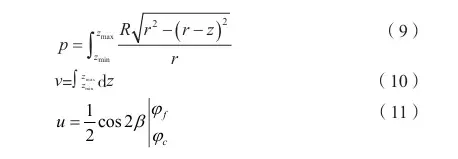
Where:
- z represents the tool axis;
- zmax and zmin represent the maximum and minimum values of the tool axis;
- r represents the radius of the arc in the corner transition section of the workpiece;
- φc represents the tool rotation angle;
- φf represents the tooth angle.
Definition of coefficient p: In simple terms, this calculates the effect of the tool on the workpiece within the “upper and lower ranges.”
v: In simple terms, this represents “how much of the tool’s height is involved in cutting.”
u: In simple terms, this quantifies the influence of “tool tooth geometric distribution + shear angle” on cutting force.
(3) Deflection Curve Equation
Establish the deflection curve equation for the corner transition section of the machined workpiece, as shown in Formula (12).

Where:
- η represents the deflection curve equation;
- x represents the measurement point for the transition deformation.
- l represents the machining depth;
- E represents the elastic modulus;
- I represents the moment of inertia.
In simple terms: This is a CNC version of a “beam bending formula.” The tool pushes the workpiece → the workpiece bends like a spring → this formula is used to calculate the bending shape.
(4) Corner Transition Deformation Quantity
Based on the above, combined with cantilever beam theory, predict the deformation quantity at the workpiece corner transition, as shown in Formula (13).

Where:
- H represents the predicted deformation quantity at the workpiece corner transition;
- D represents the tool overhang length.
Through the above steps, predict the deformation quantity at the workpiece corner transition during CNC machining.
In simple terms: this calculates “how much the workpiece is bent at the corner.” The longer the tool protrudes → the more it tends to vibrate → the greater the deformation.
Corner Transition Deformation Error Compensation
Based on the predicted deformation amount at the workpiece corner transition, corresponding error compensation processing is performed to improve the precision of CNC machining.
The deformation error compensation strategy adopted in this paper is shown in Figure 1.
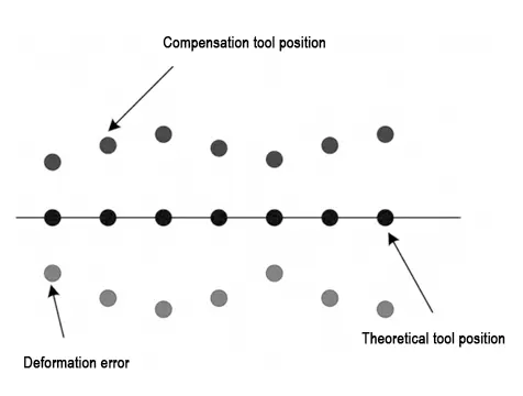
Based on the error compensation strategy shown in Figure 1, error compensation processing is performed on the workpiece corner transition deformation by modifying the CNC machining tool path trajectory.
During the actual error compensation process, considering the influence of the tool axis vector, this paper optimizes the calculation of the reference benchmark for error compensation.
The specific calculation method is shown in Formula (14).

Where:
- Y represents the reference benchmark for error compensation.
- xi
t represents the corner transition deformation point compensated at time t; - Hmax and Hmin represent the predicted maximum and minimum values of corner transition deformation, respectively.
Researchers set the reference benchmark for error compensation. They determined the optimal error compensation tool position.
This position ensures that the predicted deformation error is compensated at the correct workpiece corner transition point.
Under this compensation strategy, the tool’s posture is adjusted to perform the corresponding error compensation.
In simple terms: The above formula means, “Take the average of the maximum and minimum deformations as the correction reference,” so that the tool’s compensation is neither excessive nor insufficient but precisely centered.
Technical Application
Test Conditions
Researchers aimed to verify the practical application performance of the deformation error compensation technology designed in this paper.
They conducted a test experiment on a workpiece containing corner transition points.
The experiment verified the CNC machining corner transition deformation error compensation.
The CNC machining parameters for this test were set to verify the error compensation.
The experiment required accurate data collection.
Researchers installed a force gauge model Kistler9257B in the CNC machining test environment to measure the milling force.
The gauge provided precise milling force measurement results.
The sampling frequency of the force gauge was set to 5000 Hz to obtain the CNC machining test data for this experiment.
Technical Application Example
We applied the deformation error compensation technology designed in this paper for testing under the aforementioned test environment settings.
We calculated the milling force and cutting force of the CNC machining parameters, and Figure 2 shows the results.
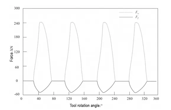
Figure 2 shows the CNC machining process of this workpiece. During this process, the milling force and cutting force exhibit a regular trend of change.
This trend indicates that the contact between the tool and the workpiece surface is relatively stable.
Based on these calculation results, the error at the workpiece corner transition was predicted and corresponding compensation was applied.
The deformation error at the corner transition during CNC machining is too small to be observed by the naked eye.
Therefore, the experiment conducted microscopic measurements of the machining parameters at the corner transition location.
These measurements yielded the results shown in Figure 3.
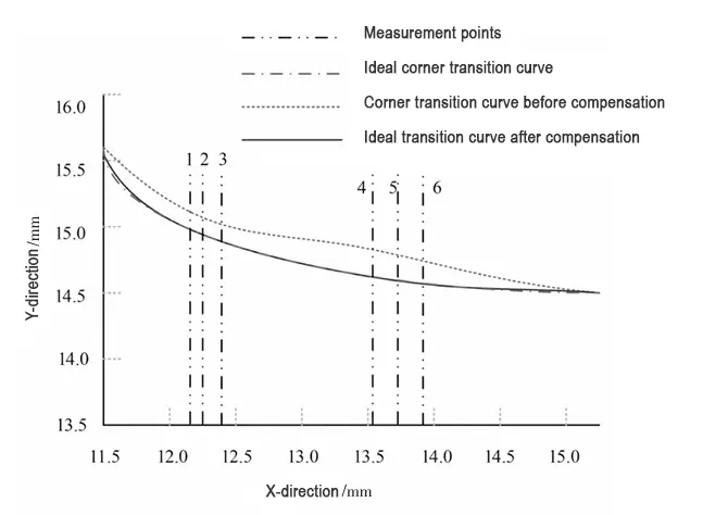
Figure 3 shows the results. The technology described in this paper compensates the CNC-machined workpiece.
It significantly reduces the deformation error at the corner transition. It produces a higher degree of overlap with the ideal corner transition curve.
This result validates the applicability of the technology described in this paper.
Comparison of Deformation Error Compensation Effects
Researchers aimed to further evaluate the performance of the technology described in this paper in CNC machining.
They conducted a deformation error compensation comparison experiment. They used the same machining parameter settings for the experiment.
The comparison methods used in this experiment were two types of machining deformation error compensation methods: one based on the curvature integral algorithm and the other based on binocular vision.
The deformation error compensation results for each method are shown in Figure 4.
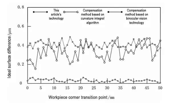
Figure 4 shows the results under each method. The technology described in this paper compensates the workpiece and significantly lowers the corner transition error.
It controls the surface difference from the ideal design processing parameters within 0.05 μm. It significantly reduces the corner transition error of the workpiece.
The technology fully considers the influence of the tool axis vector. This consideration enables compensation at more precise positions.
As a result, the technology enhances the actual machining accuracy of CNC machining.
Conclusion
This paper designs a compensation technique for corner transition deformation errors in CNC machining.
It analyzes the milling force and cutting force in CNC machining. It effectively predicts the potential corner transition deformation errors in the workpiece..
We determine the specific compensation points based on the definition of the reference benchmark and apply corresponding compensation at these points to enhance the machining accuracy of CNC machining.
FAQ
What causes deformation errors at corner transitions in CNC machining?
Deformation errors at corner transitions occur due to factors such as machine tool structure, cutting forces, temperature changes, and tool overhang, which can reduce the accuracy of the workpiece and impact assembly and performance.
Why is corner transition deformation critical in aerospace and automotive manufacturing?
High-precision fields like aerospace and automotive require exact tolerances. Deformation at corners can lead to scrap parts, additional rework, and increased costs, making compensation essential for production efficiency.
How are milling force and cutting force calculated in CNC machining?
Milling force is the direct cutting force applied by the tool, while cutting force arises from plastic deformation and material fracture. Both are calculated using differential methods, contact angles, shear plane definitions, and integrated infinitesimal elements.
What is the role of the contact angle in predicting CNC machining deformation?
The contact angle, which increases with cutting depth, determines how the tool engages the workpiece. Calculating entry and exit angles based on the contact angle helps predict corner transition deformation more accurately.
How does the deflection curve equation help in CNC machining accuracy?
The deflection curve equation models the bending of the workpiece at corner transitions using cantilever beam theory. It allows engineers to predict deformation and plan precise compensation to enhance machining accuracy.
What is CNC corner transition deformation error compensation?
This technology modifies the CNC tool path to offset predicted deformations at corner transitions. By setting a reference benchmark and adjusting the tool trajectory, it ensures precise machining without over- or under-compensation.
How does force coefficient calculation improve deformation prediction?
The comprehensive force coefficient integrates milling and cutting forces, along with tool geometry and material properties, providing a weighted measure of applied forces. This coefficient allows accurate prediction of corner transition deformations.
How is the effectiveness of deformation error compensation verified?
Effectiveness is verified through experiments using force gauges and microscopic measurements. Results show significant reduction in corner transition errors and improved overlap with ideal design curves, often within 0.05 μm accuracy.
What advantages does the technology in this study offer over other compensation methods?
Compared with curvature integral and binocular vision methods, this technique accounts for the tool axis vector, enabling compensation at more precise points and achieving higher actual machining accuracy.
Why is compensating corner transition deformation important for CNC machining efficiency?
Compensation improves workpiece precision, reduces scrap and rework, lowers manufacturing costs, extends machine tool life, and minimizes downtime, thereby enhancing overall CNC machining efficiency.

