Addressing the challenge of processing deformation in aerospace aluminum alloy thin-walled components without using heat treatment to release stress, this study analyzes and improves the issue from the perspectives of structural characteristics and process control.
We adopt effective clamping control methods to reduce the risk of deformation in thin-walled components.
Currently, most aluminum alloy thin-walled components address deformation control by employing thermal stress relief.
However, in the aerospace industry, certain aerospace aluminum alloy thin-walled parts have design requirements that prohibit thermal stress relief and constrained measurement.
If manufacturers still use conventional processing methods, they can cause deformation and vibration issues during manufacturing, resulting in a low qualification rate and poor surface quality of aerospace parts.
This paper uses specific part processing examples to analyze their structure, processing challenges, and manufacturability, develop deformation prevention measures, and explain how to control deformation in easily deformed aluminum alloy thin-walled parts without thermal stress relief.
Local Deformation Structure Control
Part Structure Analysis
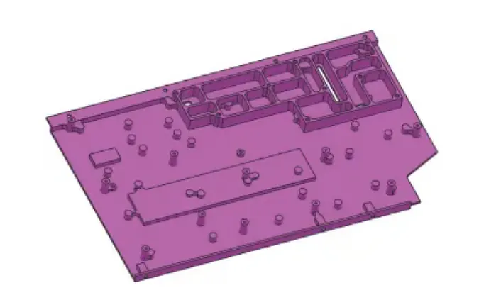
The part shown in Figure 1 has numerous reinforcing ribs in the upper right corner, which prevent deformation during processing. The lower left corner lacks reinforcing ribs, and the bottom wall thickness is only 1.6 mm, with an overall material removal rate exceeding 90%.
Suppose a two-step machining process (front and back) is directly applied. After machining, deformation may occur because the upper-right region retains stronger structural integrity, while the left side undergoes extensive material removal.
In that case, the distribution of machining stresses between the lower left and upper right corners becomes uneven, ultimately causing deformation in the thin-walled region of the lower left side without reinforcing ribs.
Machining Process Analysis
The part material is Al6061 aerospace aluminum alloy, which has properties such as lightweight, high strength, good machinability, and corrosion resistance, but it also has significant machining deformation.
To minimize deformation when machining the final part, minimize stress release as much as possible beforehand.
However, since thermal stress release is not used, engineers must consider deformation control from the overall process perspective.
During finishing operations, improper process design or inappropriate clamping methods can cause part vibration, elastic deformation, and internal stress deformation due to uneven force distribution.
To ensure no deformation occurs during machining, the process primarily focuses on three aspects: reasonable process design, deformation-preventing clamping design, and high-speed machining technology.
Adjust the process as follows: first, perform rough machining on both sides of the part, then allow natural aging, and finally finish both sides.
Considering that the part has reinforcing ribs in certain areas, the finishing process primarily uses side clamping.
Rough Machining
Throughout the rough machining process, consider several key factors. These include the cutting depth per pass, the interference of external forces on the part, and the stresses generated during machining. Careful consideration of these factors helps minimize uncontrollable issues.
(1) Fixture Handling
Before clamping, calibrate all clamping tools, including vise jaws, clamping jaws, and fixture tooling, to ensure horizontal stability. This prevents the raw material from being deformed by uneven clamping during the process.
(2) Clamping Position
Minimize the influence of external forces on the raw material. When clamping aluminum alloy raw material in its natural state using vise jaws, first perform edge processing on the clamping area.
This step ensures that the clamping surfaces remain parallel before and after roughing. This prevents deformation caused by forced clamping during installation.
(3) Front Roughing Allowance Control
Aluminum alloy materials may deform due to internal stress after removing a large amount of material. Therefore, reserve a deformation allowance of 1.5–3.0 mm. The front roughing process is shown in Figure 2.
(4) Cutting Depth per Pass During Roughing
Due to the low rigidity of aluminum alloy materials, excessive cutting depth per pass and fast machining speed can cause significant changes in the part’s internal stress.
Selecting a small cutting depth of 1.0 to 2.0 mm can reduce internal stress deformation. Compared to a significant cutting depth, a small cutting depth has a smaller cutting area, faster heat dissipation, and is less affected by thermal stress from machining.
(5) Control of Roughing Allowance on the Opposite Side
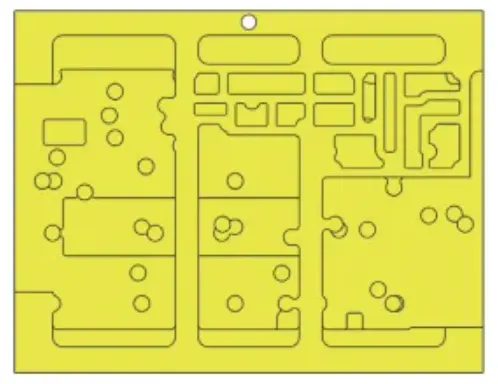
When performing roughing on the opposite side (see Figure 3), ensure that the remaining allowance on both sides is as consistent as possible, with both controlled between 1.5–3.0 mm.
During clamping, the workpiece should be held in its natural state, and the clamping force should not be too strong, with the force range controlled between 15–20 N.
(6) Roughing Process Design
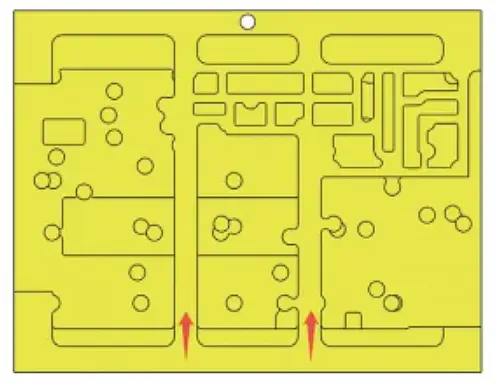
The part is a thin-walled component with a concave shape, featuring a lower middle section and higher front and rear sections.
When designing the roughing process, it is essential to incorporate clamping reinforcement ribs (see Figure 4) to ensure proper clamping during subsequent finishing operations.
This prevents deformation of the part caused by uneven force distribution when clamping the front and rear sections.
Natural Aging
Due to differences in environmental temperature between winter and summer, the deformation of parts after natural aging will also vary.
Depending on the material, rough-machined parts can be left to rest for 7–14 days based on actual conditions, during which time some of the internal stress in the aluminum alloy is released.
To avoid unfavorable deformation conditions in cold winter environments, the part storage environment can be adjusted as needed to maintain a temperature above 25°C.
Finishing
During the finishing process, it is also necessary to consider various factors from different angles to minimize uncontrollable variables.
(1) Tool Selection
Throughout the finishing process, the remaining material on the part must be removed through machining. Using different tools in different areas can lead to varying degrees of part deformation.
It is advisable to use the same tools whenever possible to ensure consistent contact surfaces between the tools and the part, as well as uniform heat distribution.
Avoid using different tools on the same continuous surface area whenever possible.
(2) Semi-finishing Clamping Method
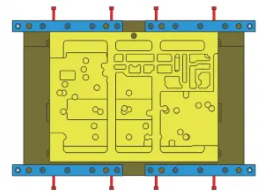
Use specialized fixtures for clamping. Place the part in its natural state into the fixture. Utilize the two reinforcing ribs reserved during rough machining to clamp the part using four parallel blocks for side clamping (see Figure 5).
Position the locking screws on the left and right sides of the part and at the locations of the two reinforcing ribs. Avoid applying excessive clamping force, with the force range controlled between 15–20 N.
(3) Control of the Locating Surface of Reference A
Place the part in the fixture in its natural state and use the same clamping method to clamp the part from the front and rear.
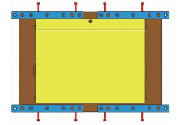
Use a small cutting depth of 1.0–2.0 mm to machine this surface and simultaneously machine two locating holes to prepare for part positioning in the next step. The front finishing is shown in Figure 6.
(4) Part Placement
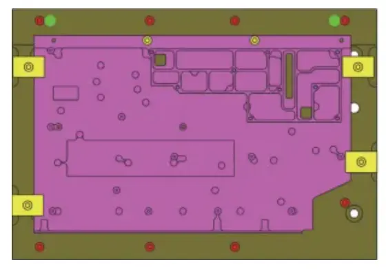
The reverse side finishing is shown in Figure 7. Using the two locating holes at the green position, naturally place the part on the dedicated fixture. Maintain flatness within 0.05 mm in its natural state. Tighten the eight screws at the red position.
When tightening the screws, do not lock one screw completely before moving on to the next. Ensure that the force is distributed evenly across all locking positions of the part.
After machining the main areas, continue machining the four clamping blocks and two screws at the newly added yellow positions to secure the regions completed until the process is finished.
(5) Front and Back Side Finishing Notes
Whether the feed rate per cut is 1.0–2.0 mm or the finishing allowance is 0.2 mm, the goal is to minimize the tensile stress caused by the tool during cutting and the thermal stress generated between the tool and the part during machining.
Before each finishing operation, naturally correct the parallelism of the clamping locating surfaces. This ensures that the part remains securely clamped on the fixture without deformation from external forces.
It also ensures that other machined areas of the part are not affected by clamping forces during processing.
Overall Deformation Structure Control
Part Structure Analysis
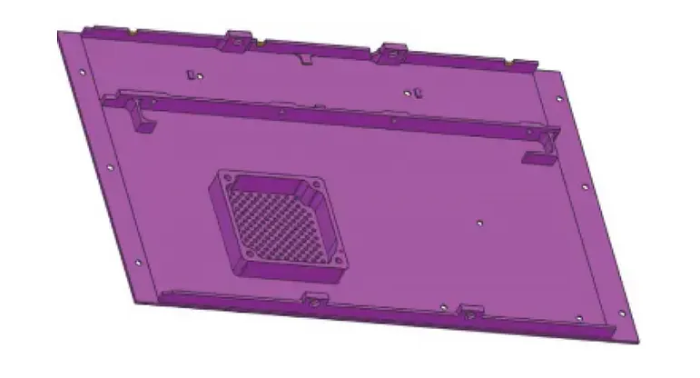
As shown in Figure 8, the part has no reinforcing ribs, with an overall wall thickness of 1.6 mm and an overall material removal rate >90%. Any area of the part may deform due to improper processing, and conventional processing methods cannot guarantee that the part will not deform.
Machining Process Analysis
The part material is Al6061 aerospace aluminum alloy, which undergoes significant deformation during machining. To control overall stress changes in the part, the overall process must also be optimized and designed.
The process is divided into the following steps: rough machining of both sides of the part before aging → natural aging → precision machining of both sides.
Considering that the entire part may deform, the finishing process adopts a reverse clamping method with suction cups.
The roughing before finishing and the preparation for natural aging refer to the process design mentioned earlier in “Local Deformation Structure Control.” The following primarily discusses the finishing process design.
Finishing
Throughout the entire finishing process, several factors must be carefully considered before machining. These include cutting depth, finishing allowance, part positioning surface clamping, and locking methods.
Proper consideration helps avoid excessive external forces that may cause part deformation. It also minimizes uncontrollable factors during machining.
(1) Locating Surface Treatment
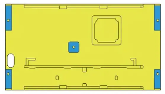
Because the part lacks suitable overall locating surfaces, reserve five auxiliary protrusions for reverse clamping during rough machining.
Before finishing, naturally parallel the surfaces of the protrusions. This ensures that the part does not deform from screw clamping forces during reverse clamping The reverse clamping position is shown in Figure 9.
(2) Reverse Clamping Fixture
The reverse clamping fixture is shown in Figure 10. Reverse-clamp the part to be machined (yellow) onto the dedicated fixture A (semi-transparent blue) using its five locating surfaces, forming combined assembly B with fixture A.
Then, mount assembly B onto the locating workbench or another corresponding dedicated fixture.
After reverse clamping, many areas of the part’s lower surface are exposed. When machining the upper surface, control the cutting depth per pass to within 1.0 mm. This prevents excessive cutting depth from causing surface vibration.
At the same time, machine the two locating holes required for the next machining step.

(3) Suction Cup Clamping
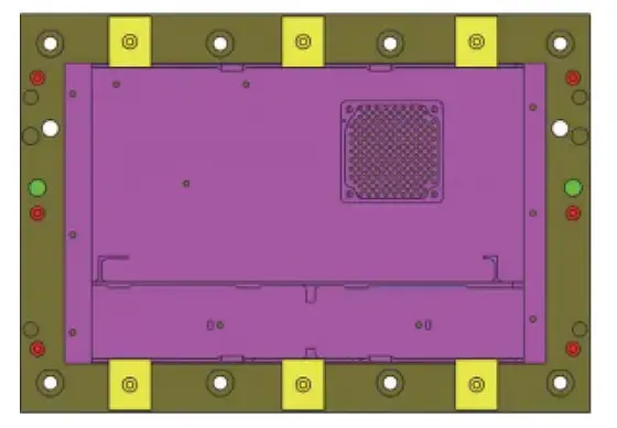
As shown in Figure 11, remove the part from the inverted fixture and clamp it using a suction cup.
Place the part into the dedicated fixture through the two locating holes at the green position, and simultaneously screw the six screws at the red position into the part surface.
Turn on the suction cup air pump switch before fully tightening the screws, then tighten all six screws.
After completing the central processing areas of the part, attach six clamping plates at the yellow positions on the front and back to secure the completed areas, and continue processing until you finish the part.
Conclusion
After processing the aluminum alloy irregular thin-walled parts according to the above process plan, inspect them strictly according to the drawing requirements. The inspection results meet the drawing specifications.
This paper presents two cases of local deformation and overall deformation, and proposes process improvements from aspects such as product structure, process route, processing parameters, and clamping methods.
Perform rough machining and natural aging to pre-release stress. Before precision machining, naturally, machine the clamping locating surfaces to control the accuracy of the locating surface reference.
During machining, use clamping methods such as side supports, reverse suspension, and vacuum cups. These measures effectively control product deformation.
In terms of process innovation and control, this study offers additional technical references for manufacturers of aerospace-grade irregular thin-walled parts that cannot be processed using thermal stress relief.
FAQ
What are the main challenges in machining aerospace aluminum alloy thin-walled components without thermal stress relief?
The main challenges include deformation, vibration, and uneven stress distribution due to the material’s low rigidity and high material removal rates. Controlling these factors requires careful process design, clamping methods, and machining parameters.
How can manufacturers minimize deformation in aluminum alloy thin-walled parts?
Manufacturers can minimize deformation by adopting effective clamping control methods, performing rough machining with deformation allowances, natural aging, and precision machining using side supports, reverse suspension, and vacuum cups.
Why is thermal stress relief often restricted in aerospace thin-walled components?
Certain aerospace design requirements prohibit thermal stress relief to preserve material properties or meet measurement constraints. This makes alternative deformation control methods essential.
What process steps are recommended to control local deformation in thin-walled aluminum parts?
Recommended steps include rough machining both sides, reserving auxiliary protrusions, natural aging to release internal stress, and finishing both sides with controlled clamping and cutting depths.
How does clamping design affect part deformation during machining?
Proper clamping design, such as using side clamping blocks, reinforcing ribs, and suction cups, ensures uniform force distribution and prevents excessive stress on delicate areas, reducing deformation risks.
What role does cutting depth play in preventing deformation?
Using small cutting depths (1.0–2.0 mm per pass) reduces stress concentration, limits vibration, and minimizes thermal effects on thin-walled aluminum components.
How does natural aging help in machining aluminum alloy thin-walled parts?
Natural aging allows internal stresses to partially release after rough machining. Resting parts for 7–14 days in controlled temperature conditions helps reduce deformation before finishing.
What finishing strategies are effective for aerospace thin-walled components?
Effective finishing strategies include using consistent tools, parallelizing locating surfaces, controlling cutting depth and allowance, and careful reverse clamping with suction cups or auxiliary supports.
How should manufacturers handle parts with uneven structural reinforcement?
Areas with reinforcing ribs maintain structural integrity, while thin regions without ribs require careful allowance, controlled cutting depth, and precise clamping to prevent localized deformation.
What are the key takeaways from this study for aerospace manufacturers?
This study provides a reference for controlling deformation in aerospace aluminum alloy thin-walled parts without thermal stress relief. Key takeaways include process optimization, natural stress release, careful clamping, and high-speed machining technology to ensure part quality.

