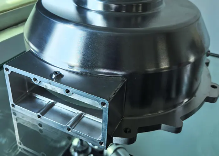
In the high-precision CNC manufacturing industry, composite products often deform easily and require high positional accuracy at specific locations.
These characteristics present several challenges during process design. Manufacturers find it difficult to control product deformation effectively.
Clamping the parts can also be problematic, as improper methods may distort the dimensions. The clamping force itself often affects the final product size.
Additionally, the process typically involves multiple steps. Operators must rely on fixtures and manual clamping when transitioning between these steps.
This reliance makes it hard to consistently meet product tolerance requirements. In mass production, these issues lead to process instability and a high defect rate.
As a result, production efficiency drops and costs increase.
As such, conducting manufacturing process research for such high-precision composite tolerance parts is highly necessary.
The author focused on a high-precision composite part with an opening that is prone to deformation. To address this, they compared traditional processing methods and designed a new process scheme.
This approach aimed to control deformation effectively and ensure the part met dimensional tolerance requirements.
By introducing the processing techniques for high-precision composite tolerance parts, this study provides a reference for the processing of similar or identical products in the future.
Comparison of Processing Methods
Traditional CNC machining of parts involves using three-axis equipment, with process-to-process coordination and fixture-based positioning to ensure dimensional accuracy.
During the process, manual re-clamping is often required, which can lead to clamping deformation during multiple clamping operations.
Traditional CNC machining has several disadvantages. When relying on fixture positioning, it often leads to cumulative precision errors between processes. These errors cause unstable product accuracy that fails to meet specifications.
In mass production, this results in high defect rates and reduced production efficiency.
Process dispersion results in a lengthy process route, requiring more equipment and workers, larger equipment footprints, increased material handling volumes, longer production cycles, and higher production costs.
The author’s designed machining process scheme adopts a process-concentrated machining and clamping approach, which addresses the shortcomings of traditional CNC machining methods.
By utilizing the rotational machining capabilities of a four-axis machine tool, processes are centralized, reducing the number of times parts need to be clamped.
After a single clamping, multiple surfaces of a part can be machined, not only shortening auxiliary time but also ensuring the relative positional accuracy of these surfaces.
This reduces the number of processes, shortens the process route, simplifies production planning and organization, thereby minimizing cumulative errors caused by excessive processes and ensuring machining accuracy.
Additionally, it reduces the number of machines and operators needed. This decrease minimizes production space, lowers labor requirements, and shortens processing time.
It also reduces the transportation workload between processes. As a result, productivity increases significantly while manufacturing costs drop.
Part Processing Technology Scheme
Part Analysis
High-precision composite tolerance part processing is shown in Figure 1.
The material of the part is AL6061-T651 aluminum alloy, an imported aluminum alloy with good strength and uniformity.
The part is used as a critical component in a three-coordinate measuring device, capable of connecting other moving components, with the function of ensuring high-precision measurement of the three coordinates.
» Dimensional and Tolerance Requirements
The part has external dimensions of 95 mm × 60 mm × 50 mm. Its flatness requirement is 0.02 mm. The two holes on the side walls must meet a coaxiality tolerance of 0.025 mm.
The axis connecting these holes must remain parallel to the surface within 0.03 mm. The two side faces, which are perpendicular to the bottom surface, must meet a perpendicularity tolerance of 0.02 mm.
Additionally, the width of the two side surfaces must be 500 mm with a tolerance of –0.025 mm. Multiple dimensions are interrelated in terms of coaxiality, parallelism, and perpendicularity.
» Machining Challenges and Process Strategy
The part has an open break in the middle, with high precision requirements and difficult clamping. To reduce processing steps, the precision requirements are achieved in a single processing operation.
Select an unimportant feature surface along the length of the part to extend the blank, creating a rectangular part blank.
Design threaded holes and locating pin holes on the extended blank for inserting bolts and locating pins, facilitating subsequent clamping and machining.
» Custom Fixture Design
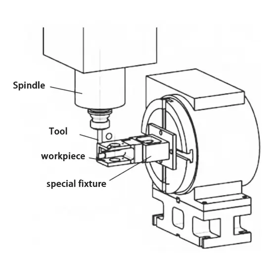
Design a specialized fixture, as shown in Figure 2.
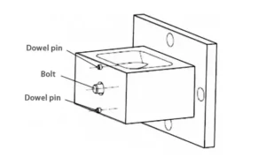
The two locating pin holes are used for positioning, and the central threaded hole is used for connection and locking.
Select a four-axis machining center and utilize its four-axis automatic rotation function to achieve multi-surface machining with a single clamping of the part.
During the machining process, rough machining is performed first, followed by semi-finishing to release part deformation.
Concentrate the part’s precision requirements on the four axes, utilizing the rotational precision along the axis to ensure consistency and stability in part production.
By adopting the proposed machining process, multiple clamping operations are unnecessary, achieving process concentration and stable precision.
Machining Process Steps
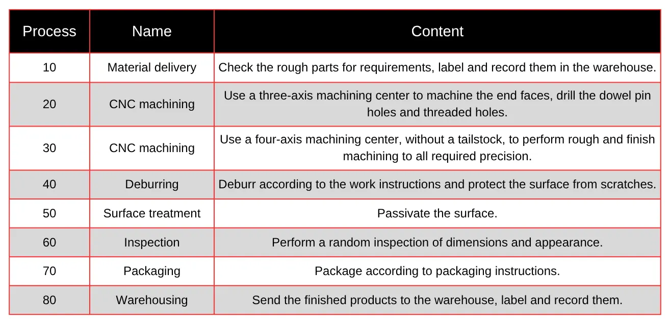
The specific machining process steps for the part are shown in Table 1.
» Key Requirements for Process Design
When designing the machining process plan for the part, four requirements must be met.
First, the dimensional accuracy requirements specified in the part drawings must be satisfied.
Second, the accuracy requirements, stability, and consistency during mass production must be ensured.
Third, production efficiency must be improved, costs controlled, and economic requirements met. Fourth, the process must be simple for operators to perform.
The specialized fixture is mounted on a four-axis machining center, and the connection between the part blank and the specialized fixture is shown in Figure 3.
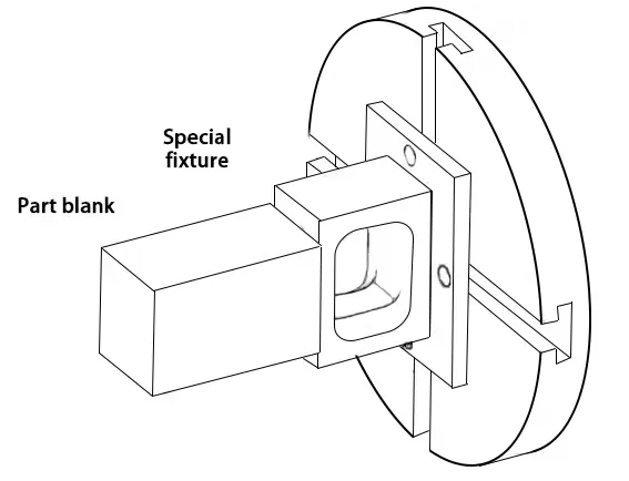
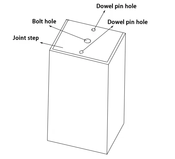
Two locating pin holes and one threaded hole are machined on the extended end face of the part blank for locating and securing the part blank to the specialized fixture.
» Locating and Securing the Part
The locating pins on the specialized fixture are designed with an interference fit relative to the part blank.
Additionally, a central bolt is used to pull the part blank backward in the opposite direction to secure it, preventing it from loosening during machining.
The shape of the specialized fixture is designed to provide sufficient operating space for the tool when tightening the bolts, while avoiding interference between the tool and the specialized fixture during machining.
The specialized fixture is securely fastened to the four-axis machining center using bolts.
» Integrated Machining Setup
After connection, the part blank, specialized fixture, and four-axis machining center form an integrated unit, allowing the part blank and specialized fixture to rotate together with the four-axis rotation.
The four-axis can rotate 360° along the axis, and the rotational positioning accuracy exceeds the precision required for the part.
Through four-axis rotation, multiple surfaces rotating around the axis can be machined.
The machining sequence for each surface is determined based on machining characteristics and precision requirements. This effectively converts the part’s precision requirements into four-axis rotational precision.
» Clamping and Machining Sequence
During machining, the clamping and positioning surface of the part is selected as the end face in the length direction.
The part’s openings, surrounding holes, and other features do not affect machining, so rough machining can be performed first according to the part’s precision requirements, followed by semi-finishing, and then finishing, all completed within a single process.
Finally, only the cut-off area with remaining allowance needs to be finished separately to complete the machining.
By adopting the designed machining process steps, the four-axis machining center can ensure the precision requirements, thereby ensuring the stability and consistency of the part during the machining process.
Specific Machining
The part blank is shown in Figure 4.
» Process 20: Preparation and Hole Machining
Perform process 20: stand the part blank upright, clamp it with a standard vise, and select one side for positioning.
Machine the end face and machine two positive tolerance locating pin holes and one threaded hole for positioning and securing the part blank to the fixture.
The locating pins on the part blank and the special fixture must be controlled to have an interference fit.
Note that the depth of the locating pin holes and threaded hole must be controlled on the extended blank part and must not exceed the net height dimension of the part, otherwise there is a risk of overcutting.
Machine a 0.5 mm step along the end face and leave a 0.5 mm allowance.
The machined step dimension is larger than the net dimension of the part’s end face to effectively ensure process safety.
The connection between the part blank and the specialized fixture has been introduced earlier and will not be repeated here.
» Process 30: Rough Machining Using Four-Axis Rotation
Perform process 30 to perform rough machining on the open slot, holes on both sides, and surrounding surfaces using four-axis rotation.
During machining, define the residual material at the connection point with the part as a reinforcing rib.
First, fully retain the reinforcing rib without cutting it, and machine all features along the four-axis rotation direction once, leaving an appropriate allowance.
The purpose of retaining the reinforcing ribs is to enhance the part’s rigidity during rough machining. These ribs help prevent tool vibration that may occur due to insufficient rigidity at the connection points.
Without adequate support, such vibrations could negatively impact machining quality and efficiency. By maintaining rigidity, the ribs enable rapid and efficient rough machining.
» Partial Removal of Reinforcing Ribs
After rough machining is complete, a portion of the reinforcing ribs is removed, as shown in Figure 5, to allow the part’s stress to be fully released in its natural state.
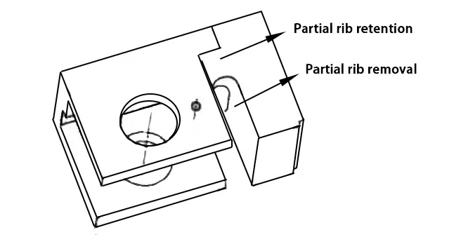
Perform finishing on the features after rough machining and fully machine all features without precision requirements specified in the drawings.
The purpose of retaining part of the reinforcing ribs is to maintain rigidity during finishing, prevent tool vibration during machining, and improve machining efficiency and surface quality of the part.
» Final Removal of Reinforcing Ribs
After all features without precision requirements specified in the drawings are fully machined, all remaining reinforcing ribs connecting the two side walls are removed, as shown in Figure 6.
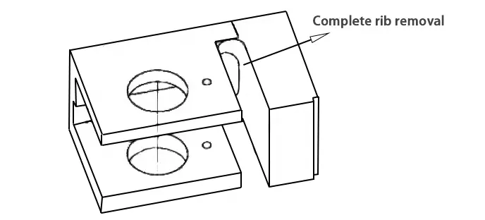
Separate the two side walls from the scrap material to completely release the deformation at the edge position, facilitating subsequent finishing operations.
» Preparation for Finishing Precision Areas
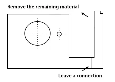
Before performing finishing operations on all precision-critical areas, all excess material that affects part deformation is completely removed to ensure that all precision requirements are not affected by deformation.
Only a segment of the boundary flush with the part and connected to the blank is retained, while the remaining areas are completely separated from the blank, effectively placing the part in a free state for finishing all reference edges and bores, as shown in Figure 7.
» Finishing with Minimal Allowance
Since rough machining has already been performed, the remaining allowance is minimal, so the part’s rigidity is fully capable of withstanding the cutting forces generated during finishing.
When finishing surfaces and holes, the machining parameters can also be adjusted to meet the drawing’s precision and surface roughness requirements.
» Final Cut-Off and Stress Control
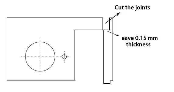
After finishing, the part is cut to separate it from the excess blank, as shown in Figure 8.
At this point, it is important to note that cutting can also generate stress, which may cause deformation of the part.
To address this, smaller tools are used, feed rate and spindle speed are controlled, and cutting is performed in layers.
A margin is left on the cutting wall for subsequent finishing, and the cutting thickness is controlled to 0.15 mm, ensuring the part does not fall directly but can be easily broken by hand without affecting dimensional accuracy, while also maintaining surface quality.
Thus, all precision requirements are completed in a single process.
» Final Touches and Post-Processing
Finally, only a light polish of the cutting surface is required to complete all machining operations.
Subsequent processes include deburring, surface treatment, and inspection.
The advantages of the designed machining process scheme include concentrating all precision requirements into a single process, simple clamping, part precision unaffected by other human factors, stable and reliable quality, and suitability for mass production.
Conclusion
The machining process scheme designed by the author for high-precision composite tolerance parts is applicable to parts that are prone to deformation, have high precision requirements, and are difficult to clamp.
The advantages of this machining process scheme lie in stress relief during processing and the conversion of part precision requirements into four-axis rotational precision through four-axis rotation, effectively ensuring part processing quality and ultimately enabling mass production.
Of course, due to cost constraints, the specialized fixture design and selected machining equipment are not yet optimal, and the machining process scheme still has room for improvement in terms of processing quality and efficiency.
Further refinements and enhancements will be pursued in the future.
FAQ
What are the main challenges in machining high-precision composite tolerance parts?
High-precision composite tolerance parts are prone to deformation and require tight positional accuracy, making it difficult to control part stability during machining. Challenges include clamping-induced distortion, multiple process steps, and maintaining dimensional tolerances during mass production.
Why does traditional CNC machining often fail to meet precision requirements for complex parts?
Traditional CNC machining typically uses three-axis equipment and manual re-clamping, which can introduce cumulative positioning errors and clamping deformation. This leads to unstable accuracy, high defect rates, and low production efficiency, especially in high-volume production.
How does four-axis machining improve the accuracy of composite tolerance parts?
Four-axis machining allows multiple surfaces of a part to be machined in a single clamping by rotating the part around one axis. This eliminates repeated repositioning, reduces cumulative errors, and ensures better consistency in relative positional accuracy.
What is the role of specialized fixtures in machining precision parts?
Specialized fixtures are designed to securely clamp the part using locating pin holes and threaded holes. They help prevent loosening or shifting during machining, minimize deformation, and ensure the part rotates accurately with the four-axis system for consistent precision.
How does the designed machining process control deformation in precision parts?
The process retains reinforcing ribs during rough machining to enhance part rigidity and reduce tool vibration. Deformation is controlled by gradually removing these ribs and excess material in stages, allowing internal stress to release naturally without compromising dimensional accuracy.
What material is commonly used for high-precision composite tolerance parts?
AL6061-T651 aluminum alloy is commonly used due to its high strength, excellent uniformity, and good machinability. It supports tight dimensional control and is suitable for parts requiring stable mechanical performance and high precision.
What are the dimensional and geometric tolerance requirements of a typical precision part?
Typical requirements include flatness of 0.02 mm, coaxiality of 0.025 mm for side holes, parallelism of 0.03 mm, and perpendicularity of 0.02 mm. Width tolerances for specific faces may also be as tight as 500 mm –0.025 mm, with several dimensions interrelated.
How does process integration benefit CNC machining of complex parts?
By integrating multiple machining steps into a single setup using four-axis machining and specialized fixtures, the process becomes more efficient. It reduces the number of machines, operators, transitions, and manual clamping, which improves productivity and lowers manufacturing costs.
What are the advantages of using reinforcing ribs in rough machining?
Reinforcing ribs add structural stability to the part during machining, especially at stress-prone areas like openings or thin walls. They help prevent tool chatter and deformation, improving roughing efficiency and surface quality before final finishing.
Can this CNC machining process be scaled for mass production?
Yes, the proposed machining scheme is designed for mass production. It ensures stable part precision by eliminating human error, reducing the number of clamping operations, and improving repeatability through fixture-guided four-axis machining.

