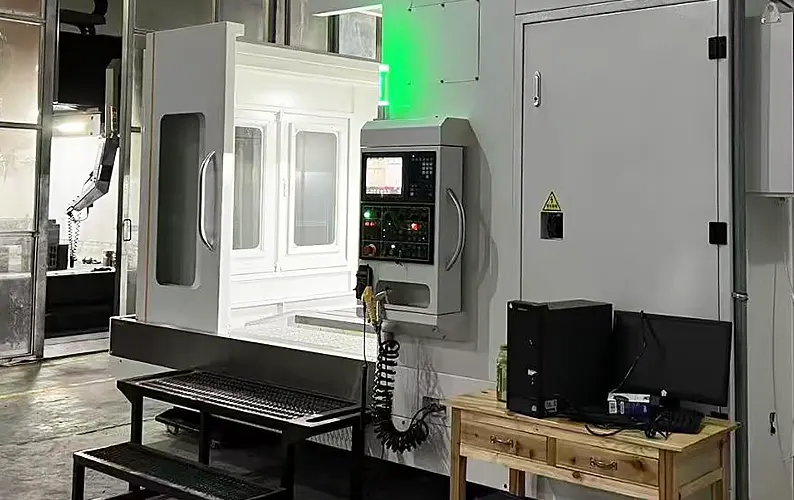
As a core component of underwater equipment, the piston rod body is designed to enhance the anti-corrosion performance by localized surfacing of nickel-based alloy, taking into account the environment and functional requirements of its use.
The surface roughness of the sealing area is required to be extremely high, so as to ensure the reliability of the metal seal.
It raises the difficulty factor of the machining process and increases the risk of product scrapping.
The rationality of the piston rod body finishing program will directly affect the processing efficiency of the product and the qualified rate of the finished product.
Analysis of processing difficulties
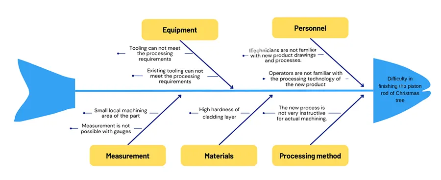
Using the brainstorming analysis strategy, combined with the processing content of the piston rod body engineering drawings of the Christmas tree, the reasons for the difficulty in finishing the piston rod body were analyzed.
This analysis covered five aspects: equipment, personnel, measurement, materials, and processing methods.
The relevant factors were generalized and organized accordingly.
A fishbone diagram was constructed to list these factors one by one. The analysis of the piston rod body finishing difficulties is shown in Figure 1.
Existing tooling can not meet the workpiece processing requirements
Considering the workpiece processing location and processing content and the matching of existing equipment, the choice of floor boring and milling machine processing.
However, due to the small size of the workpiece shape and structure, if the conventional V-iron tooling clamping, there will be a risk of exceeding the processing range of the machine tool in the implementation of certain processing content.
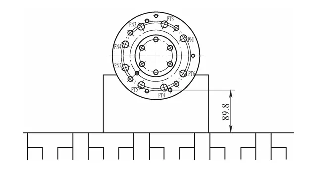
Based on the external dimensions of the piston rod body and the existing tooling, CAD was used to simulate the clamping and to sample the areas where interference may exist.
The clamping simulation of the piston rod body of the Christmas tree is shown in Figure 2. The interference area during the end face machining is illustrated in Figure 3.
The interference area on the outer cylindrical surface during the electrical connector mounting hole machining is shown in Figure 4.
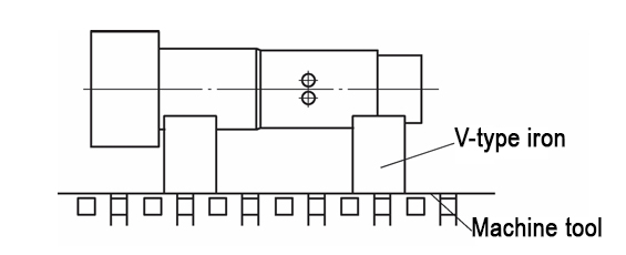
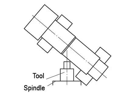
The lateral hole machining on the outer circumference of the piston rod body can be basically completed, as shown in Figure 2.
In Figure 3, the lowest machining position of the workpiece end face cladding layer is 9.8mm away from the table, close to the 90mm low machining limit of the machine tool, and there is a risk that the machining content cannot be realized;
Figure 4 shows interference between the machine tool spindle and the conventional V-shaped iron workpiece.
During the machining process, the tool hangs too far out, causing vibration and tool chatter.
Additionally, the safety clearance between the machine tool spindle and the workpiece is too small, increasing the risk of collision.
Poor machinability of the surfacing layer in the finishing area of the workpiece
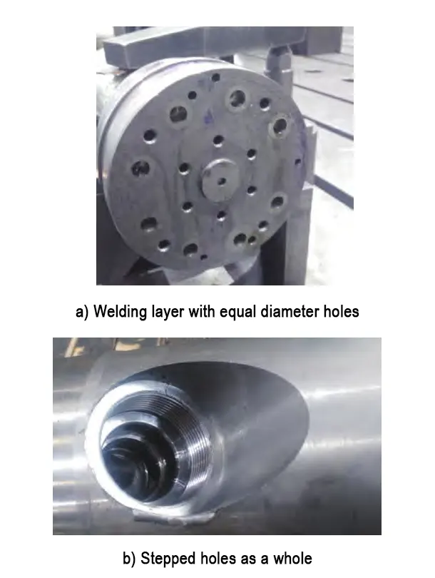
In order to improve the corrosion resistance of the local area of the piston rod body of the Christmas tree, the area of nickel-based alloy cladding, cladding layer processing is mainly isometric holes and step hole processing.
(1) Surfacing layer isometric hole processing.
It is known from the literature that corrosion-resistant nickel-based alloys have high hardness. Additionally, there are local hard spots after cladding.
To machine the isometric holes, high-cobalt drill bits with surface coatings are often used.
(2) Processing of stepped holes on the circumference.
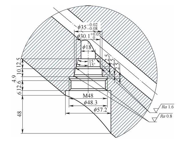
The requirements for processing the stepped holes on the circumference are shown in Figure 5. These stepped holes mainly consist of the main body with an isometric section and a transition taper hole section.
A smooth transition is required between the two sections. There must be no visible tool marks or traces at the junction.
For the machining of the tapered hole section, it is necessary to use the machine tool in conjunction with the flat rotary disk. This setup inevitably increases the cumulative error.
The machining accuracy is directly affected by this factor. Therefore, it is essential to consider optimizing the machining process.
(3) High surface quality requirements of the workpiece finishing area
The workpiece is a core component of underwater equipment and is required to operate under long-term underwater conditions. Therefore, it must have a highly reliable sealing solution to ensure normal operation.
To meet this requirement, the interface must possess excellent sealing characteristics. The multi-group metal sealing taper design demands a surface roughness value of Ra = 0.8 μm.
As a result, developing an appropriate machining program has become a key challenge.
(4) The detection of the workpiece is difficult
Due to the small external dimensions of the workpiece processing parts, conventional gauges cannot complete the inspection. As a result, it is necessary to control the external dimensions of the tool’s cutting edge.
Additionally, the machining accuracy of the machine tool and other related factors must be managed. These measures are taken to achieve equivalent detection accuracy.
(5) Operators are not familiar with the process
The workpiece, being a core component of a new product, is undergoing its processing technology for the first time. This introduces new challenges in execution.
Differences in how operators interpret the process documentation have also emerged. These discrepancies have become a risk point in the workpiece processing workflow.
Solutions
Design of supporting tooling
The machining capacity of the machine can not be changed, only through the design of new tooling, the workpiece will be clamped in the machining range of the machine.
Combined with the basic state of the workpiece to be machined, start from the following two aspects.
Protection of the machined area.
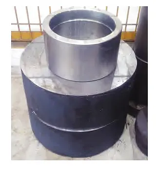
Considering that the end of the workpiece features an external thread structure that has already been machined, a positioning protection sleeve was designed.
This sleeve protects the finished thread during subsequent operations. At the same time, it ensures consistency in the clamping cylindrical size.
Existing V-shaped iron workpiece transformation.
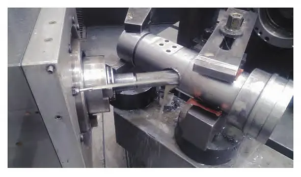
Combined with the existing support tooling V-iron, a new design of circular pads was introduced. The pad surfaces were processed using a grinder to ensure high precision.
Surface flatness and surface roughness were controlled according to the requirements of the reference pad.
The newly designed tooling is shown in Figure 6, and the application of the new tooling is shown in Figure 7.
(1) Adoption of customized tools
For drilling of carbide cladding, customized high cobalt drills with coatings are used.
For stepped holes, floor boring and milling machines generally use a flat rotary cutter head.
Considering the small size of the machining area and the required machining accuracy of the flat rotary disk, the process was adjusted accordingly.
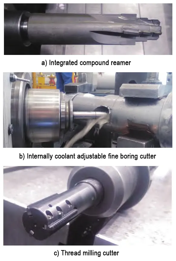
A one-piece composite reamer was adopted for improved efficiency.
An internally cooled, adjustable fine boring cutter was used to ensure precision. Additionally, a thread milling cutter was employed to enable combined machining.
The customized tooling is shown in Figure 8.
(2) Solve the machining detection problem
Through the reasonable selection of machining tools and the development of complete machining process, the realization of equivalent detection to solve the detection problem.
(3) Effective implementation of process programs
Combined with the production schedule, the process engineer carries out the technical briefing work and participates in the whole processing to ensure the effective implementation of the process program.
(4) Program implementation and results show
Promote the implementation of the solution throughout the process, the processing results are shown in Figure 9.
Conclusion
This paper focuses on the finishing difficulties of the piston rod body. It conducts a cause analysis and proposes process improvements.
A combined machining program is developed, along with modifications to the existing tooling. The solution involves integrating a forming milling cutter and a thread milling cutter.
This approach addresses the challenges in machining the end face of the surfacing layer, particularly with equidistant holes and circumferential stepped holes.
The results provide both theoretical and practical support for machining similar products.
If mass production occurs in the later stage, the quality, efficiency, and cost problems caused by tool wear will be highlighted.
Therefore, the process optimization of this product needs to be continuously promoted in the upgrading of CNC machine tools and the application of integrated forming reamers.
Supplementary
What is a Christmas tree?
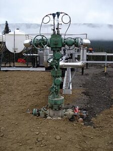
In the oil and gas industry, a Christmas tree (often just called a tree) is an assembly of valves, spools, fittings, and other equipment installed at the wellhead to control the flow of oil or gas from a well.
Why is it called a “Christmas tree”?
The name comes from its appearance—with multiple valves and branches extending in different directions, it resembles a decorated Christmas tree.
Functions of a Christmas Tree:
Controls flow of oil/gas from the well.
Monitors pressure in the wellbore.
Provides access for injection of chemicals or gas.
Allows well intervention or servicing.
Ensures safety by isolating the well in emergencies.
Types of Christmas Trees:
Vertical Tree – Valves are stacked vertically above the wellhead.
Horizontal Tree – Designed with valves on the side, often used in subsea operations.
Christmas Tree vs. Wellhead:
Wellhead: Structural component at the surface of the well.
Christmas Tree: Installed on top of the wellhead; controls the flow and pressure.
Onshore vs. Subsea Christmas Trees:
Onshore/Surface Trees are installed above ground.
Subsea Trees are installed on the seafloor, used in offshore drilling.
Summary:
A Christmas tree in the oil industry is a critical control system that manages the flow of oil or gas from a well, helps monitor well conditions, and allows safe operation during production or intervention.
FAQ
What are the main challenges in finishing piston rod bodies for underwater equipment?
Finishing piston rod bodies is difficult due to the high surface roughness requirements, hard nickel-based alloy surfacing, complex hole structures, risk of tool vibration, limited machine clearance, and the inability to use standard gauges for inspection. Each of these factors increases machining complexity and scrap risk.
Why is surface roughness critical in piston rod machining?
Surface roughness is critical—especially Ra ≤ 0.8 μm—because the piston rod operates in a high-pressure underwater environment. A smooth sealing area ensures metal-to-metal seal integrity, which is essential for leak prevention in subsea oil and gas equipment like Christmas trees.
What makes nickel-based alloy surfacing hard to machine?
Nickel-based alloys are corrosion-resistant but extremely hard, especially after surfacing. They often contain hard spots that challenge traditional tooling, cause rapid tool wear, and require specialized high-cobalt drills and fine boring cutters for precise machining.
How does customized tooling improve machining of piston rod bodies?
Customized tools like internally cooled fine boring cutters, one-piece composite reamers, and thread milling cutters enhance accuracy, reduce cumulative error, and minimize vibration. This allows effective machining of complex features like stepped holes and isometric hole patterns in difficult surfacing layers.
What is the role of specialized fixturing in this machining process?
Standard V-iron tooling risks interference and machine collisions due to the small size of piston rod bodies. Custom fixtures, such as precision-ground circular pads and protective sleeves, ensure secure clamping, protect pre-machined threads, and maintain positional accuracy within the machining range.
How is interference between the spindle and workpiece avoided?
Interference is mitigated using CAD simulations to identify potential collisions. Customized clamping fixtures reposition the workpiece to avoid tool overhang and reduce the risk of spindle vibration or crash during tight-tolerance machining operations.
How is precision maintained when conventional gauges can't be used?
Due to size constraints, external measurements are replaced with indirect detection methods like controlling tool cutting edge dimensions and machine tool accuracy. This approach ensures equivalent measurement precision, even without traditional gauges.
What is a Christmas tree in the oil and gas industry, and how does the piston rod relate to it?
A Christmas tree is a valve assembly controlling oil/gas flow at a wellhead. The piston rod body is a critical, pressure-resistant component used within this assembly. Its precise machining ensures sealing and structural integrity under extreme underwater conditions.
Why is operator training essential for machining new product components?
The piston rod body is part of a newly developed product. Without prior experience, operators may misinterpret technical documents. Involving process engineers in briefings and active machining ensures accurate execution and reduces processing errors.
What long-term strategies are recommended for improving piston rod body machining?
Continuous process optimization is crucial—this includes adopting integrated forming reamers, upgrading CNC machines, and refining the machining program based on production data. These steps ensure better quality control, cost-efficiency, and scalability for mass production.

