In engineering and precision manufacturing, accurate measurement is not merely an ideal—it is an operational necessity. Among the various tools developed to meet this demand, the Vernier caliper stands out as a fundamental instrument for acquiring precise linear measurements. Its enduring relevance, despite the rise of digital tools, is a testament to both its simplicity and effectiveness.
Vernier calipers are indispensable in sectors such as mechanical engineering, industrial manufacturing, aerospace, automotive design, and scientific research. Whether in a machine shop, a university lab, or a quality control station, professionals and students alike rely on this instrument for reliable data acquisition.
This guide aims to provide engineers, machinists, students, and quality inspectors with a comprehensive understanding of how to read a Vernier caliper accurately. From its historical development to the intricacies of its scale system, we’ll break down each aspect to demystify its usage and reinforce confidence in its application.
A Brief History of Vernier Calipers
• Origin of the Vernier Scale
The concept of the Vernier scale was introduced by French mathematician Pierre Vernier in 1631. His invention addressed the limitations of traditional linear measurement methods by enabling users to interpolate readings between the smallest divisions on a scale. This innovation allowed for the accurate detection of minute differences, revolutionizing scientific measurement.

• Development of Calipers
The earliest calipers were simple, compass-style devices used to compare lengths and transfer dimensions. Over time, these evolved into sliding calipers that could measure both internal and external dimensions. The integration of Vernier’s scale transformed these tools into high-precision instruments capable of readings as fine as 0.02 mm or 0.001 inch, depending on the model.
• Modern Usage
Today, Vernier calipers come in analog and digital forms, each serving distinct roles across industries. While digital calipers offer convenience and rapid readings, analog Vernier calipers remain essential for environments requiring durability, independence from batteries, and a deeper understanding of mechanical measurement fundamentals.
Anatomy of a Vernier Caliper
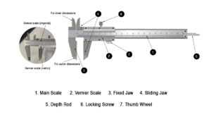
To master the use of a Vernier caliper, one must first understand its components and their functions:
• Main Scale
The main scale resembles a traditional ruler and is typically marked in either millimeters or inches. It provides the base measurement and is etched into the caliper’s fixed body.
Vernier Scale
The Vernier scale is a secondary sliding scale that runs parallel to the main scale. It allows the user to read fractional parts of the smallest main scale division, enhancing the resolution of the instrument. The number of divisions on the Vernier scale is carefully designed to provide this increased precision, commonly to the nearest 0.02 mm or 0.001 inch.
• Fixed Jaw
This component is stationary and attached to the main scale. It serves as the reference point from which all measurements are taken.
• Sliding Jaw
The sliding jaw moves along the main scale and contains the Vernier scale. It opens or closes to encompass the object being measured, whether it’s an external diameter, internal width, or depth.
• Depth Rod
The depth rod extends from the end of the caliper as the sliding jaw moves. It is used to measure the depth of holes, slots, or recesses accurately—an essential feature in engineering designs where multi-dimensional accuracy is required.
• Locking Screw
Once the desired measurement is set, the locking screw can be tightened to hold the position of the sliding jaw. This is particularly useful for transferring dimensions or recording consistent measurements during quality control.
• Thumb Wheel
Located near the sliding jaw, the thumb wheel allows for smooth and controlled movement along the scale. This facilitates fine adjustments and ensures that pressure applied during measurement remains consistent.
Working Principle
The caliper gauge comprises a base scale and a vernier scale. The vernier scale can be adjusted to match the actual dimensions of the measured object. Secure the screw to the main scale.
The main scale and vernier scale can be functionally divided into inner jaws and outer jaws.
The former is used to measure the width and inner diameter of objects, while the outer jaws measure the thickness and outer diameter.
The depth gauge and vernier can be used to measure object depth. Results obtained using calipers consist of the main scale reading and the distance between main scale lines, along with the difference between vernier scale lines.
During use, the graduation value and precision must be determined to ensure data accuracy.
Example of Precision and Scales
For example, on a precision caliper with a graduation of 0.02 mm, the numbers 1 through 9 represent the inner jaw, frame, set screw, housing, main scale, depth gauge, depth measuring surface, vernier scale, and outer jaw, respectively.
The main scale and auxiliary scale form the primary components. The scale is fixed, while the auxiliary scale can be moved according to measurement requirements.
The main scale is calibrated in millimeters (mm), with each division representing 1 mm. The total length of the main scale is 49 mm.
The auxiliary scale divides the main scale’s total length into 50 equal parts. Each auxiliary division differs from the main scale by 0.02 mm, indicating a precision of 0.02 mm.
During measurement, align the zero points of both the main and auxiliary scales. The intersection of their scale lines indicates the measurement result.
The integer value from the main scale combined with the fractional value from the auxiliary scale equals the total dimension of the calibration block, representing the total dimension of the workpiece being measured.
How to Use a Vernier Caliper
Vernier calipers are versatile instruments capable of measuring multiple dimensions with high precision. Understanding the correct usage for each measurement type is critical to ensure reliability and repeatability in engineering applications.
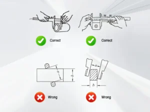
• External Measurements
To measure the external dimensions—such as the outer diameter of a shaft or the width of a block—use the outside jaws of the caliper:
Open the jaws and place them around the object.
Gently close the jaws until they make contact with the surfaces.
Use the thumb wheel to fine-tune the position without applying excessive force.
Tighten the locking screw to secure the measurement before reading.
• Internal Measurements
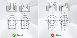
To measure internal dimensions—such as the diameter of a hole—use the inside jaws:
Insert the inside jaws into the feature to be measured.
Expand the jaws until they contact the internal surfaces.
Ensure the caliper is perpendicular to the axis of the hole for an accurate reading.
Lock the jaws in place before taking the measurement.
• Depth Measurements
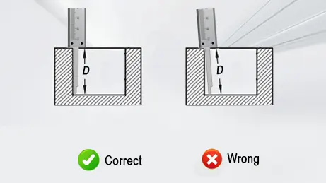
The depth rod is used for determining the depth of blind holes, recesses, or cavities:
Extend the depth rod by moving the sliding jaw backward.
Insert the end of the caliper flat against the reference surface.
Continue sliding until the rod touches the bottom of the feature.
Lock the position and record the reading.
• Step Measurements
Step dimensions—such as the offset between two surfaces—are measured using the step-measuring faces on the back of the caliper:
Position the fixed jaw against the upper surface.
Lower the sliding jaw onto the lower step.
Lock and read the scale to obtain the vertical difference.
• Marking with Calipers
While not primarily a layout tool, calipers can assist in precision marking.
Scraping Method: Use the fixed and sliding jaws to lightly scribe a line on a metal surface.
Pencil Method: For less abrasive marking, a pencil or fine-tip marker can be run along the edge of the jaw.
Use caution when marking, especially on finished parts, to avoid surface damage.
How to Read a Vernier Caliper
Correctly reading a Vernier caliper involves a systematic approach. Whether using metric or imperial units, follow this step-by-step procedure to ensure accuracy:
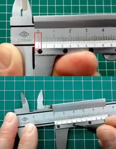
• Step 1: Calibrate the Zero
Close the jaws fully and check if the zero on the Vernier scale aligns with the zero on the main scale.
If the zeros do not align, note the zero error. This must be accounted for during measurement (positive or negative).
Calibration should be checked regularly to maintain measurement integrity.
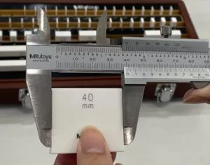
• Step 2: Position the Object
Open the caliper and place the object between the appropriate jaws or under the depth rod.
Ensure proper orientation and consistent pressure.
Once in position, tighten the locking screw to secure the reading.
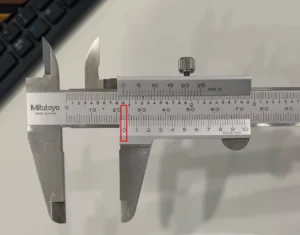
• Step 3: Read the Main Scale
Observe the main scale just before the zero mark on the Vernier scale.
Record this value. It represents the main measurement in millimeters or inches, depending on the scale type.
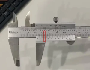
• Step 4: Read the Vernier Scale
Look along the Vernier scale for the line that aligns exactly with any line on the main scale.
Identify the number of this line on the Vernier scale.
Multiply this number by the least count of the caliper (commonly 0.02 mm or 0.001 in).
• Step 5: Add Both Readings
Use the formula:
Final Measurement = Main Scale Reading + (Vernier Scale Alignment × Least Count)
Example (Metric Caliper with 0.02 mm Least Count):
Main scale reading = 24.00 mm
Vernier scale alignment = 7th division
Final measurement = 24.00 + (7 × 0.02) = 24.14 mm
This technique ensures precision up to two decimal places, crucial for tight-tolerance engineering work.
Formula for Reading Vernier Calipers
Understanding the formula behind Vernier caliper readings is crucial for accurate interpretation of measurements. The calculation combines values from both the main scale and the Vernier scale.
• Standard Formula:
Total Reading=Main Scale Reading+ (Vernier Scale Alignment×Least Count)
Main Scale Reading: The value on the fixed scale just before the Vernier scale zero.
Vernier Scale Alignment: The index or tick mark on the Vernier scale that aligns precisely with a tick on the main scale.
Least Count (LC): The smallest measurable increment on the caliper.
• Understanding the Alignment Index
The alignment index is determined by identifying the mark on the Vernier scale that best aligns with any mark on the main scale. For instance:
If the 7th tick on the Vernier scale aligns with a mark on the main scale, and the least count is 0.01 mm:
Vernier Contribution=7×0.01=0.07 mm
This value is added to the main scale reading to give the total measurement.
• Examples:
Metric Example
Main scale reading: 13.00 mm
6th tick on Vernier aligns with the main scale
Least Count (LC): 0.02 mm
Total=13.00 mm+(6×0.02)=13.12 mm
Imperial Example
Main scale reading: 1.200 in
3rd tick on Vernier aligns
Least Count: 0.001 in
Total=1.200 in+(3×0.001)=1.203 in
The formula remains the same across metric and imperial systems; only the units and least count vary depending on the scale configuration.
What Is Least Count?
• Definition:
The least count of an instrument is the smallest value it can measure with accuracy. In the case of Vernier calipers, it represents the difference between one main scale division and one Vernier scale division.
• Formula:
Least Count = Smallest Main Scale Division/Number of Vernier Divisions
This formula arises from the differential measurement principle—where the Vernier scale interpolates values smaller than what the main scale can resolve.
• Examples:
Metric Vernier Caliper
Smallest main scale division: 1 mm
Vernier scale divisions: 10
Least Count=1/10=0.1 mm
Some higher-precision calipers may have 50 divisions:
Least Count=1/50=0.02 mm
Imperial Vernier Caliper
Smallest main scale division: 0.1 in
Vernier scale divisions: 10
Least Count=0.1/10=0.01 in
• Importance in High-Precision Measurements
Least count determines the resolution of the caliper. A smaller least count allows finer measurement discrimination, which is vital in applications like:
Tolerance inspection in precision machining
Quality control in aerospace component fabrication
Research involving material deformation or thermal expansion
An engineer must always know the least count of the instrument being used, as it dictates both the accuracy of readings and the level of confidence in critical measurements.
Compensating for Zero Error
Even a high-quality Vernier caliper can develop zero error over time due to wear, debris, or improper handling. Failing to account for this can systematically offset all your measurements.
• Types of Zero Error
Positive Zero Error
Occurs when the Vernier zero lies to the right of the main scale zero when the jaws are fully closed.
This means the caliper is “reading too much,” so the zero error must be subtracted from the measured value.
Negative Zero Error
Happens when the Vernier zero is to the left of the main scale zero.
The caliper is “reading too little,” so the zero error must be added to the measurement.
• Formula for Compensation
Correct Reading=Measured Value−Zero Error
Where the sign of the zero error is positive or negative depending on its direction.
• Worked Example (Zero Error Correction)
Suppose you’re measuring a component and obtain a measured value of 25.16 mm. However, when you close the jaws fully, the Vernier zero aligns at 0.04 mm to the right of the main scale zero.
This indicates a positive zero error of +0.04 mm.
Apply the correction:
Correct Reading=25.16 mm−0.04 mm=25.12 mm
If, instead, the Vernier zero was to the left by 0.02 mm, the error would be −0.02 mm, and the corrected value would be:
25.16 mm−(−0.02 mm)=25.18 mm
Always check for zero error before measurements, especially in precision applications.
Common Mistakes When Reading Vernier Calipers
Even experienced professionals can make errors when using Vernier calipers. Awareness of these common pitfalls enhances measurement accuracy and reliability.
1. Zero Error Ignorance
Mistake: Taking measurements without checking for zero error.
Impact: Results in a consistent offset in all readings.
Solution: Always verify zero alignment before use and apply the appropriate correction.
2. Parallax Error
Mistake: Reading the scale from an angle instead of directly above.
Impact: Misinterpretation of the alignment between scale marks.
Solution: Align your eye perpendicularly to the scales during measurement.
3. Scale Misalignment
Mistake: Not ensuring the jaws are square to the object.
Impact: Leads to incorrect readings, particularly in round or irregular shapes.
Solution: Use even pressure and check jaw alignment visually before locking the caliper.
4. Reading the Wrong Scale
Mistake: Confusing metric and imperial scales, especially on dual-scale calipers.
Impact: Major discrepancies in recorded values.
Solution: Clearly identify and consistently use one unit system throughout the task.
5. Improper Use of Jaws
Mistake: Using external jaws for internal measurements or vice versa.
Impact: Inaccurate results due to tool geometry not matching the application.
Solution: Understand the purpose of each jaw set and apply accordingly:
Outside jaws for external measurements.
Inside jaws for internal dimensions.
Depth rod for depth.
Step feature for offset or step dimensions.
Avoiding these common mistakes ensures precise, repeatable measurements—essential in engineering, manufacturing, and quality assurance environments.
Operating Environment and Usage Range
While Vernier calipers are precision tools, their accuracy is sensitive to environmental factors and handling practices. Proper usage conditions ensure consistent performance and prolong tool life.
Working Temperature Range
Ideal operating range: 5°C to 40°C (41°F to 104°F)
Thermal expansion of the metal can distort readings if the caliper or the object being measured is too hot or cold.
Best practice: Allow calipers and parts to acclimate to room temperature before measurement.
• Humidity
High humidity or exposure to moisture can lead to corrosion, especially in carbon steel or non-stainless calipers.
Storage: Keep calipers dry, ideally in a protective case with silica gel packets to absorb moisture.
Cleanliness
Dust, oil, or metal shavings on the jaws or scale can skew readings.
Before use: Wipe the jaws with a soft cloth and check the scale for debris.
Avoid applying too much cutting fluid or grease near the measuring surfaces.
• Handling Tips
Avoid dropping the caliper—shock can displace the scale or affect alignment.
Don’t overtighten the locking screw, which may lead to internal stress or warping.
Recalibrate periodically, especially in industrial environments or after impact.
Practice Problems & Worked Examples
To reinforce the reading method, here are five common scenarios with solutions:
• Example 1: Basic External Diameter
Object: Shaft
Main scale reading: 36.0 mm
Vernier alignment: 4th division
Least Count: 0.02 mm
Reading=36.0+(4×0.02)=36.08 mm
• Example 2: Internal Groove Width
Object: Retaining ring groove
Main scale reading: 15.0 mm
Vernier alignment: 9th tick
Least Count: 0.02 mm
15.0+(9×0.02)=15.18 mm
• Example 3: Positive Zero Error Adjustment
Measured reading: 42.10 mm
Zero error: +0.04 mm
42.10−0.04=42.06 mm42.10 – 0.04 = \textbf{42.06 mm}42.10−0.04=42.06 mm
• Example 4: Complex Scenario with 9th Tick
Main scale: 28.0 mm
Vernier alignment: 9
LC: 0.01 mm
28.0+(9×0.01)=28.09 mm
• Example 5: Depth Measurement
Object: Blind hole
Main scale: 12.0 mm
Vernier alignment: 5
LC: 0.02 mm
12.0+(5×0.02)=12.10 mm
Practice with physical parts and verified dimensions is highly recommended to build muscle memory and confidence.
Vernier Caliper Calibration
Vernier caliper calibration is the process of measuring precision and correcting errors in vernier calipers, serving as a critical task in ensuring product quality during actual production. The following provides an analysis and explanation of the content and significance of vernier caliper calibration.
Content of Vernier Caliper Calibration
Vernier caliper calibration is a comprehensive task requiring strict adherence to relevant standards, combined with usage conditions, to ensure scientific organization and implementation. The following sections analyze calibration practices from three perspectives: calibration cycle, calibration content, and calibration requirements.
» Calibration Intervals for Vernier Calipers
Calibration is performed when vernier calipers exhibit noticeable wear or damage during use to ensure measurement accuracy.
Under current conditions, calibration intervals are typically determined based on factors such as usage frequency, operating methods, and the caliper’s wear level.
Generally, calipers with high usage frequency and severe wear require shorter calibration intervals, while those used infrequently with minimal wear may have longer intervals. However, most calibration cycles are set within one year.
» Content of Vernier Caliper Calibration
The calibration of vernier calipers primarily covers appearance, caliper body, measuring jaws, and zero-point error.
Appearance inspection involves a detailed examination of the vernier caliper for scratches, dents, or other surface damage.
Prior to calibration, disassemble the caliper components and clean each part with gasoline. Subsequently, inspect all surfaces for scratches or dents.
If cosmetic damage or defects are present, use a fine file to polish the affected areas and eliminate imperfections.
Gap calibration focuses on determining whether the caliper surface—particularly the scale face—exhibits scratches.
For scaled surfaces with scratches, sandpaper should be used to polish the scale surface of the vernier caliper. The calibration of the measuring jaws primarily involves inspecting the inner jaws.
In this regard, the appropriate maintenance method should be selected based on the type of inner jaw being calibrated.
For knife-edge inner jaws, inspect wear on the inner jaw edges, grind worn areas to restore smoothness, and adjust or replace components like screws and nuts.
For cylindrical inner jaws, assess overall wear and repair worn sections using chrome plating or welding.
Zero-error calibration primarily involves adjusting the zero mark on the vernier caliper to ensure accurate readings from both the main scale and vernier scale.
Before calibration, align the main scale and vernier scale to verify their zero marks are precisely matched. If misalignment occurs, use a small hammer or similar tool to adjust the vernier scale until both marks align correctly.
If the zero mark becomes blurred due to prolonged use and cannot be restored by regrinding, the circular aperture on the caliper may be widened and lengthened. Alternatively, the base hole position can be adjusted to perform zero-value correction.
» Requirements for Vernier Caliper Calibration
Calibration of vernier calipers primarily involves grinding, polishing, and component replacement. Given that vernier calipers are precision instruments with stringent accuracy requirements, meticulous and standardized operations strictly adhering to relevant standards are essential during actual calibration.
Environmental conditions must ensure optimal temperature and humidity at the calibration site to prevent measurement errors caused by these factors.
Beyond controlling environmental variables, calibration procedures themselves require standardized protocols. These primarily follow the relevant requirements for vernier caliper calibration outlined in JJG 30—2012 “General Caliper Calibration Regulations.”
During actual verification, key focus should be placed on the outer jaw closing gap and the parallelism or perpendicularity between the measuring surfaces of the jaws and the workpiece surface.
The outer jaw closing gap primarily refers to controlling the gap between the outer jaws to reduce measurement errors and ensure accuracy.
This is because if the upper ends of the jaws contact while the lower ends have gaps during verification, significant measurement errors can occur.
When verifying the positional relationship between the jaw measuring surface and the workpiece surface, inspect the perpendicularity between the upper jaw and the main body of the vernier caliper to ensure they remain perpendicular to each other.
If the vernier caliper has both upper and lower jaws, separate error verification must be performed on each jaw to enhance the overall precision of the caliper.
Significance of Vernier Caliper Verification
Vernier caliper verification is the process of validating the instrument’s accuracy and measurement precision. Regular verification serves four primary purposes:
» First, it ensures measurement accuracy.
Regular calibration guarantees that the precision and measurement accuracy of the vernier caliper meet standard requirements, ensuring the reliability of measurement results.
» Second, it enhances product quality.
Vernier calipers are widely used in manufacturing, machining, and related industries. Their precision and measurement accuracy directly impact product quality. Regular calibration improves product quality.
» Third, it reduces measurement errors.
As precision measuring instruments, vernier calipers are susceptible to external factors like frequent use and transportation vibrations. Regular calibration minimizes measurement errors and improves accuracy.
» Fourth, it fulfills quality management requirements.
Industries such as automotive and electronics manufacturing demand exceptionally high precision and quality standards. Regular calibration of measuring tools is mandatory to ensure products meet these stringent quality management requirements.
Common Faults in Calibration and Their Countermeasures
As analyzed above, vernier caliper calibration demands relatively high technical standards and involves numerous calibration tasks.
Although personnel can conduct vernier caliper calibration according to established rules and promptly identify and address tool issues, certain faults and problems still arise.
These issues occur during actual calibration and affect its progress and effectiveness.
Specifically, the following common faults frequently occur during vernier caliper calibration.
Common Faults and Countermeasures for the Main Scale
» Handling Main Scale Bending Faults
During use, the main scale of a vernier caliper may suddenly bend. Analysis reveals multiple potential causes for this issue.
For instance, excessive force applied by operators during use or collisions between the caliper and other objects can cause the main scale to bend.
To resolve this issue, the main scale can typically be placed on a flat surface and tapped to restore its original shape.
If the bending is severe, specialized tools may be required for correction.
Simultaneously, repair personnel must ensure proper protection of the vernier caliper during handling to prevent additional damage to the caliper or other components.
» Troubleshooting Misalignment of Main Scale Reference Surface Flatness and Parallelism
Vernier calipers are widely used in university laboratories and metrology units. In such environments, operational impacts must be considered.
For instance, high usage frequency causes friction between the main scale and the measuring scale, leading to deviations in the straightness and parallelism of the main scale’s reference surface.
When the main scale and measuring scale continuously rub against each other, their non-parallel alignment causes displacement at the ends of the measuring scale, resulting in significant measurement errors.
To resolve this issue, maintenance personnel can grind the gap between the two scales using heavy petroleum.
This restores their straightness and parallelism to meet the requirement of being on the same plane, effectively solving the problem and ensuring measurement accuracy.
Malfunctions Caused by Improper Usage and Countermeasures
» Handle Damage Troubleshooting
A common malfunction in vernier calipers arises from improper usage during actual length measurements.
Proper use requires positioning both jaws at opposite ends of the target object.
However, operators often fail to grasp key usage principles, leading to improper handling during preparation and subsequent damage to the jaws, compromising quality and performance.
Analysis indicates that jaw damage primarily results from excessive force applied during measurement, causing gaps to form during closure.
When jaw damage occurs, repair personnel must first verify the caliper’s precision.
Specialized tools should be used to compress and grind the jaws, enabling the caliper to be reset to zero.
Additionally, after repair, the gap between the two jaws must be measured to ensure no gaps form during closure.
This safeguards the caliper’s functionality and guarantees measurement accuracy.
» Troubleshooting Gap Between Sliding Frame and Main Scale
Another common issue during caliper use involves gaps between the sliding frame and main scale.
Some operators control the caliper with their thumb, causing repeated friction along the caliper’s sides.
This prolonged friction can cause inaccurate readings and increase the gap between the sliding frame and main scale, compromising measurement precision.
Upon encountering this issue, technicians should assess the caliper. Inspect it to determine the extent of wear, examining both the surface and the gap for significant damage.
For calipers with minor wear, technicians should repair them by shimming.
When significant wear occurs, replacing the sliding frame is necessary to ensure the caliper functions effectively and maintains measurement accuracy.
Deep Measurement Area Failures and Countermeasures
» Troubleshooting Wear on the Main Scale
Wear on the depth gauge or the depth measurement groove mating with the main scale can cause the depth gauge to swing during depth measurement.
To effectively address this issue, analyze the straightness of the scale.
If straightness is found to be unreasonable, calibration is required.
If significant lateral movement is observed in the side scale, use a punch to secure it tightly.
When the sounding scale shows wear, drill a hole and insert a pin, then rivet the tail end of the sounding scale to the center of the scale groove.
If the main scale height exceeds the depth gauge height, tap the top of the depth gauge with a wooden mallet.
This creates an extension zone for grinding allowance, followed by honing with an oilstone.
When the end face of the depth gauge is not coplanar with the measuring base of the main scale, a surface grinder is typically employed.
However, specialized fixtures must be used during processing to ensure precise positioning.
This safeguards the functionality of the vernier caliper and prevents adverse effects from wear.
» Caliper Wear Troubleshooting
During depth measurement with vernier calipers, the narrow measuring surface of the depth rod causes wear on surrounding caliper components.
Even with careful handling, cumulative wear occurs over time. To address this issue, technicians must tap the measuring surface of the depth rod with a striking tool.
After deformation occurs in the side pull rod, use a specific abrasive tool to grind the surface, restoring it to its original condition.
For vernier calipers exhibiting wear after prolonged use, the frame must be disassembled and the measuring rod replaced with a new one to ensure reliable operation.
Conclusion: Reading Vernier Calipers – A Wrap-Up
Reading a Vernier caliper is a core skill for every engineer, technician, or quality inspector. Mastery lies in understanding its structure, principles, and correct application.
• Summary Checklist
Identify and understand each component (main scale, Vernier scale, jaws, depth rod).
Read the main scale and Vernier alignment systematically.
Use the reading formula and account for the least count.
Always correct for any zero error.
Practice regularly to develop confidence and precision.
• Final Note
While the concept may initially seem mechanical, true proficiency comes with repetition, reflection, and awareness. With consistent hands-on experience, the Vernier caliper becomes not just a tool but an extension of the engineer’s eye for precision.
FAQ
What is a Vernier caliper and why is it important in precision engineering?
A Vernier caliper is a precision measuring tool used to obtain highly accurate linear measurements. It's vital in engineering, manufacturing, and scientific research for its ability to measure external, internal, step, and depth dimensions with fine resolution, often down to 0.02 mm or 0.001 inch.
Who invented the Vernier caliper and what was its original purpose?
The Vernier scale was invented by Pierre Vernier in 1631 to improve measurement accuracy by allowing interpolation between scale divisions. It revolutionized scientific and industrial measurement by enabling more precise readings than standard rulers.
What are the main parts of a Vernier caliper and their functions?
Key components include the main scale (provides the base measurement), Vernier scale (adds finer resolution), fixed and sliding jaws (for external and internal measurements), depth rod (for depth measurements), locking screw, and thumb wheel for control and accuracy.
How do you read a measurement on a Vernier caliper?
To read a Vernier caliper:
Note the main scale reading just before the Vernier zero.
Identify the aligned line on the Vernier scale.
Multiply this number by the least count.
Add both values using:
Final Reading = Main Scale + (Vernier Division × Least Count).
What is the least count of a Vernier caliper and how is it calculated?
The least count is the smallest measurement a caliper can read. It's calculated as:
Least Count = Smallest Main Scale Division ÷ Number of Vernier Divisions.
Common values are 0.02 mm (metric) or 0.001 inch (imperial).
How do you compensate for zero error in a Vernier caliper?
Check if the Vernier zero aligns with the main scale zero when closed.
If the Vernier zero is to the right, subtract the error.
If to the left, add the error.
Correct Measurement = Reading − Zero Error.
What are common mistakes to avoid when using a Vernier caliper?
Mistakes include ignoring zero error, misreading from an angle (parallax error), using the wrong jaws, or confusing metric and imperial scales. Always align the caliper properly and apply consistent pressure for accurate readings.
Can a Vernier caliper measure internal and depth dimensions?
Yes, Vernier calipers can measure internal diameters using the inside jaws and depths using the depth rod. Each component is designed to ensure accurate readings across a variety of features and geometries.
How does temperature or environment affect Vernier caliper accuracy?
Temperature changes can cause thermal expansion, affecting accuracy. Use calipers within the recommended 5°C to 40°C range and allow them to acclimate to room temperature. Keep the tool clean and dry to avoid rust or contamination.
Why do professionals still use analog Vernier calipers despite digital alternatives?
Analog Vernier calipers are durable, battery-free, and foster a deep understanding of measurement principles. They're preferred in educational settings and harsh industrial environments where reliability and hands-on accuracy are critical.

