CAM Programming and Simulation for Complex Parts
⚙️ 1. What Is CAM Programming for Complex Parts?
CAM (Computer-Aided Manufacturing) programming is the process of converting a 3D CAD model into CNC machine instructions (G-code).
For complex parts — such as turbine blades, impellers, molds, and medical implants — this involves multi-axis toolpaths, precise surface control, and simulation to ensure collision-free machining.
✅ In essence:
CAD model → CAM software → Toolpath → Simulation → CNC code (G-code)
🧩 2. Why “Complex Parts” Need Advanced CAM
| Feature |
Example |
CAM Challenge |
| Freeform surfaces |
Aerospace turbine blades |
Multi-axis surface milling |
| Deep cavities |
Injection molds |
Tool reach, chip evacuation |
| Thin walls |
Medical housings |
Vibration, deflection |
| Multi-face machining |
Engine blocks |
Automatic repositioning / re-clamping |
| High-precision geometry |
Optical molds, implants |
Sub-micron accuracy & finish |
Complex parts require 5-axis or hybrid machining, specialized toolpaths, and simulation to prevent tool crashes.
💻 3. Main CAM Software Used
| Software |
Notable Features |
| Siemens NX CAM |
High-end multi-axis machining, aerospace-grade |
| Autodesk PowerMill |
Advanced 5-axis toolpath control for molds/dies |
| Mastercam |
Widely used; strong in toolpath optimization |
| CATIA CAM |
Excellent for surface machining in aerospace/automotive |
| HyperMill (OPEN MIND) |
Strong collision checking and smooth surface finishing |
| Fusion 360 CAM |
Affordable, cloud-based simulation and toolpathing |
| Esprit / GibbsCAM |
Good for hybrid mill-turn and Swiss-type machines |
🧠 4. CAM Programming Workflow for Complex Parts
Step 1: Import CAD Model
-
Load the 3D geometry (STEP, IGES, or native CAD file).
-
Check for missing surfaces or geometry errors.
Step 2: Define Stock and Fixtures
-
Specify raw material shape and how it’s held (vise, chuck, fixture).
-
Important for accurate simulation later.
Step 3: Feature Recognition & Machining Strategy
-
CAM software automatically detects features like holes, pockets, or bosses.
-
Programmer defines toolpaths:
-
3-axis roughing
-
5-axis contouring
-
Rest machining
-
Finishing passes
Step 4: Toolpath Generation
Step 5: Simulation & Verification
Step 6: Post-Processing
-
Converts internal toolpath data into G-code specific to your CNC machine and controller (Fanuc, Siemens, Heidenhain, etc.).
Step 7: NC Simulation (Optional but Critical)
🎯 5. Key CAM Simulation Types
| Simulation Type |
Purpose |
| Toolpath simulation |
Visual check for correct cutting sequence |
| Stock removal simulation |
Ensures correct final geometry |
| Collision detection |
Prevents crashes between tool, holder, fixture |
| Machine simulation |
Simulates 3D movement of actual CNC axes |
| Time & cost estimation |
Optimizes cycle time and tool wear |
💡 6. Benefits
✅ Avoids Costly Crashes — simulation prevents spindle or tool damage.
✅ Optimizes Machining Time — toolpath simulation fine-tunes feeds and speeds.
✅ Improves Surface Finish — smoother toolpaths, consistent chip load.
✅ Shortens Setup Time — digital twin allows full virtual testing.
✅ Supports Lights-Out Machining — safe unattended runs.
⚙️ 7. Advanced Strategies for Complex Parts
| Strategy |
Description |
| 5-Axis Swarf Milling |
Cutting with the tool’s side surface for smooth finishes. |
| Adaptive Clearing (Dynamic Milling) |
Maintains constant tool load — faster roughing. |
| Rest Machining |
Removes leftover material from previous operations efficiently. |
| Tool Orientation Control |
Maintains optimal tool contact angle on curved surfaces. |
| Hybrid Additive/Subtractive |
Combines laser deposition + milling for complex shapes. |
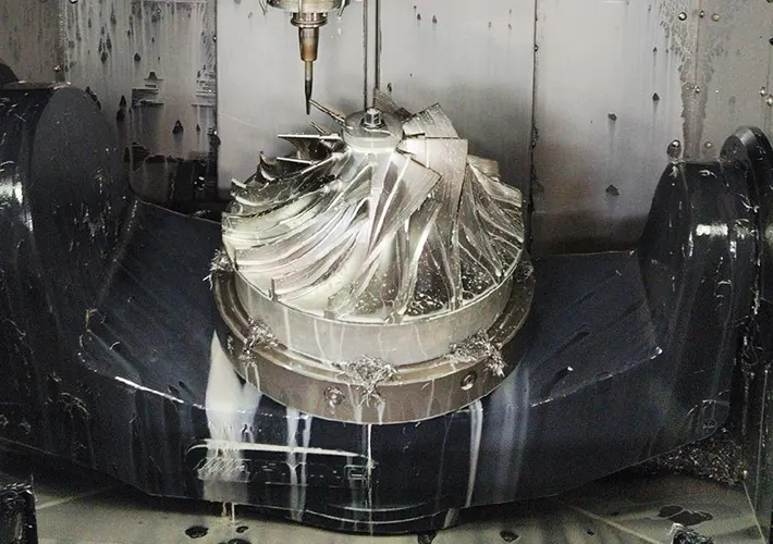
🚀 8. Example Application
Turbine Blade Machining Workflow
-
Import CAD blade geometry
-
Create 5-axis roughing & finishing toolpaths
-
Run material removal simulation
-
Check collisions between tool, shank, and fixture
-
Optimize tool entry/exit angles
-
Post-process to G-code for 5-axis machine
-
Machine actual blade with minimal risk
🏭 9. Industries Using Complex CAM Programming
-
Aerospace → Blades, impellers, housings
-
Automotive → Cylinder heads, molds
-
Energy → Turbine disks, pump impellers
-
Medical → Orthopedic implants, dental components
-
Tool & Die → Injection molds, die-casting cavities
🔍 10. Future Trends
-
AI-driven CAM optimization (adaptive feeds, automatic toolpath selection)
-
Digital twins for full machine simulation
-
Cloud-based collaboration for global teams
-
CAM-integrated inspection (probing simulation and verification)