In aircraft engines, to improve oil-gas separation efficiency and reduce lubricating oil consumption, the ventilation system of the lubrication system must be connected to the atmosphere via an oil-gas separator.
By adopting a unique axial vent design, the need for an external vent pipe and its interface with the aircraft is eliminated, thereby simplifying the structure.
Compared to the front vent design, the rear vent has a more complex structure and serves as a critical component of the aircraft engine lubrication system.
Its function is to recover lubricating oil; the flow of lubricating oil within the vent is relatively complex, making sealing performance a crucial requirement for the parts.
The quality of the assembly’s sealing performance is directly related to the dimensional accuracy and machining quality of the parts;
This paper analyzes the structure and function of the parts.
The target is to guarantee sealing performance and product machining quality. Multiple items need to be inspected and assessed.
They include processing methods, tooling and fixtures, as well as cutting tools.
These inspections ensure the finished parts satisfy design requirements.
Meanwhile, all relevant technical specifications can be fulfilled.
Structural Features
The aftercooler assembly is a critical component of the low-pressure turbine shaft in an aircraft engine compressor rotor.
This assembly consists of the aftercooler body, the vane sleeve, the oil-gas separator, and other auxiliary components.
The oil-gas separator is located in a deep groove at the tail end of the aftercooler.
It is secured by a pin and connected to a cover plate, which is then welded to the main body via TIG welding to form a single unit.
The aftercooler main body features four precision outer circles, with a coaxiality requirement of 0.02 mm.
Two of these are located at the tail end, adjacent to the welded areas, where the dimensional tolerance is 0.022 mm.
One available processing option is the conventional approach. It carries out TIG welding after machining operations.
Adopting this method will trigger severe precision dimension deformation.
Consequently, precision dimensional tolerances cannot be secured. The coaxiality requirement also fails to be guaranteed.
These dimensional quality characteristics possess great stability relevance.
Their status directly influences the sealing performance of the component.
Enhancing the machining quality of these precision dimensions is the key problem that must be solved for this workpiece.
Analysis of Challenges
1. Collapse of Internal Cavity Bosses Caused by Laser Selective Melting of Raw Material
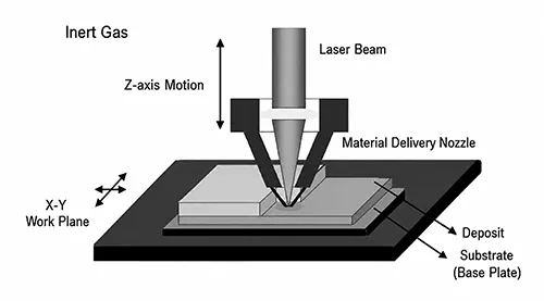
The laser selective melting forming process is illustrated in Figure 1.
Before scanning, a horizontal powder spreading roller evenly spreads metal powder onto the substrate;
The laser beam selectively melts the powder in specific areas according to 3D contour data, forming the contour of the current layer; then the elevating platform is lowered by one layer’s thickness;
The powder roller spreads metal powder over the previously processed layer;
The control program loads the data for the next layer for processing;
This manufacturing process is carried out repeatedly layer upon layer. Its purpose is to produce the metal component.
All operations are performed within an inert gas environment.
This setup stops titanium alloy from reacting with impurity gases under high temperature.
As a result, the chemical composition of titanium alloy workpieces conforms to technical specifications.
Metal 3D printing technology can be adopted to manufacture titanium alloy components.
This approach greatly raises the utilization efficiency of titanium alloy raw materials.
In addition, it tackles technical bottlenecks existing in conventional titanium alloy casting.
Typical difficulties include tough melting and forming conditions.
Workpieces are also prone to contamination from ceramic crucibles and gaseous elements.
All these problems can be effectively overcome by the new technology.
There are structural constraints inherent to the part. Meanwhile, laser selective melting technology has certain shortcomings.
The rear vent body features a boss with comparatively thin inner wall.
During the layer-by-layer forming process, collapse defects emerged at the boss position.
Auxiliary supports could not be arranged in the forming process. Furthermore, subsequent heat treatment aggravated component deformation.
Consequently, the upper surface of the boss could not be machined. This led to the occurrence of material shortage defects.
The merits and drawbacks of additive manufacturing were fully evaluated.
Traditional subtractive machining methods were also taken into account.
A combined scheme integrating the two processes was put into use.
These two technologies complement each other. As a result, the relevant defects were eliminated.
2. Deformation of Precision Outer Diameter Dimensions
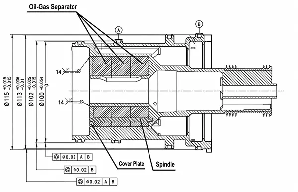
A three-stage oil-gas separator is arranged inside the deep groove on the end face.
It is connected to the cover plate by pins. Subsequently, the cover plate is joined to the ventilator main body through TIG welding.
An integrated assembly is formed in this way (see Figure 2).
During welding, the high-temperature molten pool causes deformation of the precision outer diameter dimensions, making it impossible to ensure coaxiality and dimensional accuracy of the parts;
Therefore, it is necessary to optimize the process sequence and operation details to eliminate the impact of welding stresses on the machining accuracy of the parts.
3. The Oil-Gas Separator Cannot Be Installed Properly
Based on an analysis of the part’s structural characteristics, as well as the machining and assembly processes, there are three main reasons why the oil-gas separator cannot be installed properly:
(1) The end-face groove is deep and involves intermittent turning, resulting in rapid tool wear.
The high impact forces cause the tool to deflect, leading to a “flared” profile after machining.
This creates a small clearance at the bottom during assembly, causing the part to “jam.”
Unreasonable feed parameters and spindle speed during machining caused cold work hardening on the machined surfaces of the parts.
The rough surface of the parts, combined with the “honeycomb-like” structure of the mating oil-gas separator, resulted in a small clearance during assembly, creating “sticking” and preventing proper installation.
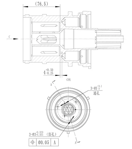
(2) Three through holes with a diameter of Ø30+0.1 and a depth of 4+0.5-0.25, as well as three blind holes with a diameter of Ø3+0.02+0.005, need to be machined at the bottom of the rear vent slot. The holes are located at the bottom of a deep groove.
The length-to-diameter ratio of the machining tool is relatively large at +0.5 +0.02.
Blind holes inside the end-face groove suffer from positional deviation.
After pins are assembled, their mounting positions shift from the nominal location.
This brings about interference between the small holes on the oil-gas separator and the pins. Eventually, the jamming phenomenon occurs.
(3) There is a circular transition at the bottom of the groove for the rear ventilator where the oil-gas separator is installed, but the body of the oil-gas separator lacks a chamfer.
This causes interference with the circular transition, preventing proper installation; the cover plate protrudes above the base surface, making assembly impossible.
The problems mentioned above need to be resolved. Multiple aspects should be optimized and controlled.
These aspects include tool materials for machining, cutting parameters, and the processing method for holes on the end face.
These improvement measures aim to eliminate assembly jamming faults.
Process Optimization
Add “Ribs” to Address the “Collapse” of the Inner Bore Boss
The inner bore boss extends significantly and assumes a “cantilevered” state during 3D printing.
During layer-by-layer deposition, influenced by the laser melting temperature and the part’s structure, “collapse” occurs at this location.
Due to the narrow internal cavity, adding removable support structures from the bottom would make it impossible to remove the part after printing;
Taking into account structural considerations as well as the manufacturability and operability of machining processes, “ribs” were added to the upper end of the boss to generate “diagonal tensile force” and prevent “collapse.”
These ribs are subsequently removed via traditional machining, which is a relatively simple and efficient process;
By combining additive manufacturing with traditional subtractive machining, we have resolved the issues associated with 3D printing this part.
Optimized Ventilation Duct Fabrication Process Plan
The assemblies need to undergo TIG welding. In addition, the outer diameters of the parts demand tight dimensional tolerances.
The target is to reduce the influence of TIG welding on part dimensional deformation.
Therefore, the axial datum of each single part shall be guaranteed in rough machining. This arrangement can avoid misalignment of the components.
Allowances are left for the remaining precision dimensions, and precision finishing is performed after the assembly has been TIG welded to minimize the impact of welding heat on part deformation.
This process not only reduces the effects of welding deformation but also avoids issues of inconsistent reference surfaces caused by repeated clamping, thereby ensuring the machining quality of the parts.
Solutions for “Sticking” During Oil-Gas Separator Installation
1. Selecting Appropriate Cutting Tools and Cutting Parameters
Expensive ceramic inserts or CBN inserts are not feasible.
After a comprehensive comparison of efficiency, cost, and quality, YG8 brazed carbide turning tools and CNC-coated carbide inserts are the most suitable choices for machining.
Regarding the selection of tool geometric parameters, to ensure the tool remains sharp, a positive rake angle should be selected, and the clearance angle should be appropriately increased.
Regarding the selection of cutting parameters, turning generates a large amount of cutting heat and significant cutting forces.
When using YG8 brazed carbide turning inserts, the spindle speed should be set to 25 r/min, and the cutting depth should be set to ap = 0.1–0.2 mm. and a feed rate of f = 0.1–0.2 mm/r; for finishing operations, the feed rate should be f = 0.02–0.06 mm/r.
Select an appropriate cutting fluid to reduce friction during the cutting process, lower cutting temperatures and tool wear, and improve tool durability and cutting efficiency, ensuring the surface quality of the machined product and reducing machining costs.
During the machining process, it is essential to use fixtures with good rigidity and a lathe with high rigidity.
Practice has proven that these cutting parameters and tool materials can meet the machining requirements of the parts.
Of course, if the rigidity of the entire machining system can be further improved, and if more powerful equipment and better tool materials are available, the cutting parameters can be optimized even further.
2. Ensuring Hole Positional Accuracy Through Optimization of Machining Methods, Fixtures, and Cutting Tools
(1) Machining Process Optimization
When machining three Ø3+0.02+0.005 blind holes and three Ø3+0.5-0.25 through holes at the bottom of a deep groove (see Figure 3), because the holes are located at the bottom of the deep groove, the tool protrudes significantly during machining.
Additionally, since the exit is angled, the drill bit is subjected to force on only one side, causing positional deviation, resulting in poor hole positional accuracy.
Therefore, adjustments were made to the machining sequence by changing the original drilling and reaming process to drilling, milling, and reaming; a specialized milling-reaming combination tool was selected.
Without adding any additional machining steps, the use of this new tool effectively ensured the positional accuracy of the holes, and the problem of hole position deviation was easily resolved.
(2) Optimization of Cutting Parameters
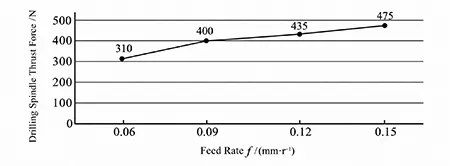
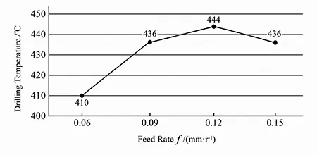
Based on the relationship graph between axial force, feed rate, and cutting temperature (see Figures 4 and 5), it can be seen that when the feed rate is constant, the axial force gradually decreases as the spindle speed increases;
When the spindle speed increases from 1200 r/min to 1500 r/min, the axial force remains essentially unchanged.
This is because 3D-printed titanium alloy is a typical hard-and-brittle material.
When the spindle speed increases, the temperature in the drilling zone rises;
The softening effect caused by the temperature rise outweighs the strain-hardening effect, causing the material’s yield stress to decrease, and thus the axial force decreases;
When the feed rate increases, the amount of workpiece material removed per revolution by a single cutting edge increases, leading to higher energy consumption and heat generation, which in turn raises the temperature in the drilling zone;
However, once the feed rate exceeds a certain value and the temperature in the drilling zone rises to a certain range, the workpiece material will exhibit a temperature-induced softening effect.
Although the volume of workpiece material removed by the cutting edge per revolution increases, the drilling resistance does not increase significantly; therefore, the temperature change remains minimal.
Based on various considerations, selecting a rotational speed of 1,200 r/min and a feed rate of 0.1 mm/r when machining holes can effectively resolve issues such as tool chipping, poor surface quality, and positional tolerance deviations.
(3) Optimization of Fixtures and Cutting Tools
The machining of this part originally used face clamping.
When machining small holes at the bottom of grooves, it was necessary to avoid the clamping plate; therefore, the tool length had to exceed 150 mm.
Due to the tool’s high length-to-diameter ratio, cutting forces caused vibration and tool deflection during machining, resulting in positional deviations in the holes;
By adopting center clamping and using an extended tool shank that extends into the interior of the part, the tool’s overhang is reduced.
A tool length of only 85 mm is required, which improves the rigidity of the tooling system and ensures more stable hole positioning.
(4) By modifying the Structure of the Oil-gas Separator
An unmachined chamfer at the very bottom of the crude oil-gas separator interfered with the transition arc of the vent body during assembly, preventing it from being properly seated.
By adding a chamfer to the bottom end of the oil-gas separator, clearance was created between it and the housing’s arc, thereby resolving the assembly issue.
Machining Results
Through exploration and research into the machining process for this part, a low-stress machining technique for 3D-printed titanium alloy assemblies was developed.
By modifying the machining process, cutting tools, and clamping methods, the problem of positional deviation in deep slot holes was resolved;
By using high-performance equipment to consolidate multiple machining operations, we eliminated positioning errors caused by repeated clamping; this simplified the process and facilitated implementation.
Inspection of the rear vent revealed that all the issues mentioned above were effectively resolved.
Both dimensional and technical specifications met the requirements of the design drawings; the coaxiality of the precision outer circle reached 0.016 mm, and the positional accuracy of the deep slot holes also reached 0.03 mm;
All characteristic dimensions fall within the acceptable range, and the surface roughness of the deep grooves and outer circumference also meets the design requirement of Ra 1.6 μm.
The “sticking” issue with the oil-gas separator has also been resolved.
Conclusion
The process route of the rear vent body was adjusted and optimized.
Fixtures and cutting tools were properly deployed. Meanwhile, refined process control measures were implemented.
All characteristic dimensions were guaranteed to satisfy design requirements.
The adverse effect of welding stress on coaxiality and outer diameter dimensional accuracy was eliminated.
Machining tools, fixtures and cutting parameters were adjusted and optimized.
This improvement not only raised the machining efficiency. It also solved several existing problems.
These problems include the positional precision of deep groove holes, surface roughness, and part deformation.