
Z-axis tool setting is a critical operation in CNC machining center operation, directly affecting machining accuracy and production efficiency.
Proper tool setting ensures that the tool’s position relative to the workpiece coordinate system is precisely established, which is essential for achieving dimensional accuracy in finished parts.
This article systematically introduces several common Z-axis tool setting methods used on machining centers, including two on-machine tool setting approaches and an off-machine tool presetting method combined with on-machine setting.
It also covers supplementary techniques such as the test cut method, lever-type dial indicator tool setting, and Z-axis measuring device tool setting, along with the procedures for entering tool offset data into the machine control system.
Each method is evaluated in terms of accuracy, efficiency, cost, and practical applicability, providing operators with a comprehensive reference for selecting the most suitable tool setting approach based on specific production requirements.
Z-Axis Tool Setting on a Machining Center
There are generally three methods for Z-axis tool setting on a machining center:
On-Machine Tool Setting Method 1
This tool setting method determines the relative positions of each tool and the workpiece in the machine coordinate system one by one through tool setting.
The specific steps are as follows.
(1) Compare the lengths of the tools, identify the longest one as the reference tool, perform Z-axis tool setting, and set the resulting tool setting value (C) as the Z value in the workpiece coordinate system; at this point, H03 = 0.
(2) Mount tools T01 and T02 onto the spindle in sequence. Perform tool setting to determine the values of A and B as length compensation values.
(This method differs from Method 3 in that it does not directly measure tool compensation but instead determines it through sequential tool setting.)
(3) Enter the determined length compensation value (the length of the longest tool minus the lengths of the remaining tools) into the setup screen.
The positive or negative sign is determined by G43 or G44 in the program; this is typically denoted as G44H—.
When G43 is used, the length compensation is a negative value.
This tool setting method offers high efficiency and accuracy with minimal investment, but it makes writing process documentation inconvenient and has a certain impact on production organization.
Method 2 for On-Machine Tool Setting
The specific steps for this tool setting method are as follows:
(1) Set up the XY-axis alignment as described earlier.
Enter the offset values for the X and Y terms in G54, and set the Z term to zero.
(2) Mount the tool T1 to be used for machining onto the spindle. Align the Z-axis using a block gauge.
Once the tool is properly tightened, read the Z-axis value Z1 from the machine coordinate system.
Subtract the height of the block gauge and enter the result into the length compensation value H1.
(3) Mount tool T2 onto the spindle. Align it using a block gauge, read the value Z2, subtract the height of the block gauge, and enter the result into H2.
(4) Follow the same procedure to align all tools Ti using the block gauge;
Subtract the block gauge height from Zi and enter the result into Hi.
(5) When programming, use the following method for compensation:
- T1;
- G91 G30 Z0;
- M06;
- G43 H1;
- G90 G54 G00 X0 Y0;
- Z100;
- …(The following describes the machining process using Tool No. 1, continuing until completion)
- T2;
- G91 G30 Z0;
- M06;
- G43 H2;
- G90 G54 G00 X0 Y0;
- Z100;
- …(Complete machining instructions for Tool No. 2)
- …M5;
- M30;
Off-Machine Tool Presetting + On-Machine Tool Setting
With this tool setting method, the axial and radial dimensions of each tool are first precisely measured off-machine using a tool presetter to determine the length compensation value for each tool.
Then, the longest tool is used to perform Z-axis tool setting on the machine to establish the workpiece coordinate system.
This tool setting method offers high accuracy and efficiency, facilitates the preparation of process documentation and production planning, but requires a significant investment.
Entering Tool Offset Data
(1) The tool offset data obtained from the above steps—specifically, the X, Y, and Z values of the programming coordinate system origin in the machine coordinate system—must be manually entered into G54–G59 for storage.
The procedure is as follows:
① Press the [MENU OFFSET] key.
② Use the cursor keys to navigate to the workpiece coordinate system (G54–G59).
③ Press the [X] key to enter the X-coordinate value.
④ Press the [INPUT] key.
⑤ Press the [Y] key to enter the Y-coordinate value.
⑥ Press the [INPUT] key.
⑦ Press the [Z] key to enter the Z-coordinate value.
⑧ Press the [INPUT] key.
(2) Tool offset values are typically entered into the machine via MDI (Manual Data Input) before program debugging. The general procedure is as follows:
① Press the [MENU OFFSET] key.
② Use the cursor keys to navigate to the offset number.
③ Enter the offset value.
④ Press the [INPUT] key.
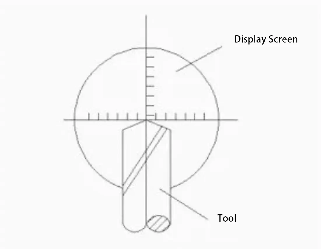
Tool Setting Using the Test Cut Method
The test cut method for tool setting is simple, but it leaves marks on the workpiece and offers lower setting accuracy;
It is suitable for tool setting during rough machining of parts. The procedure is the same as that used with a mechanical edge finder.
Tool Setting with a Lever-Type Dial Indicator
Lever-type dial indicators offer high tool-setting accuracy, but this method is relatively cumbersome and inefficient.
It is suitable for tool setting during the finishing of holes (or surfaces), but is not recommended for rough machining of holes.
The tool-setting procedure is as follows:
Use a magnetic mount to attach the lever-type dial indicator to the machining center’s spindle, positioning the indicator head close to the hole wall (or cylindrical surface).
When the dial head completes one full rotation and the needle’s deflection falls within the allowable tool setting error—such as 0.02—the rotational center of the spindle is considered to coincide with the center of the hole being measured.
Enter the X and Y coordinate values from the machine coordinate system at this point into G54.
Z-Axis Tool Setting
Considering the practicality of tool setting, the top surface of the workpiece is typically used as the origin of the Z-axis in the workpiece coordinate system.
When the top surface of the part is too rough to serve as a precise reference for tool setting, the vise or worktable may be used as the reference to define the origin of the Z-axis in the workpiece coordinate system;
The workpiece height is then entered as an upward offset in G54 or an extended coordinate system.
In-machine tool Z-axis tool setting primarily involves several methods, including Z-axis probe tool setting, tool block tool setting, and trial cutting tool setting.
Tool Setting with a Z-Axis Measuring Device
Tool setting with a Z-axis measuring device offers high accuracy.
It is particularly efficient for setting multiple tools on-machine in milling machining centers, requires minimal investment, and is well-suited for single-part machining.
When performing Z-axis tool setting for single-tool machining on a machining center—which is similar to tool setting on a CNC milling machine and does not involve length compensation—follow these steps:
①. Install the tool to be used for machining;
②. Move the tool directly above the workpiece, use the Z-axis probe to measure the distance between the workpiece and the tool, and record the current Z-axis reading (Z) in the machine (mechanical) coordinate system;
③ Subtract the height of the Z-axis measuring device at that moment (e.g., 50.03 mm) from the Z value, then enter the measured value into the Z field under OFFSET SETTING -> Coordinate System -> G54;
④ Run G90 G54 G0 X0 Y0 Z100; check whether the alignment is correct.
Conclusion
In summary, Z-axis tool setting on machining centers encompasses a range of methods, each with distinct advantages and limitations.
On-machine tool setting methods offer high efficiency and accuracy with lower investment but may complicate process documentation and production organization.
The off-machine tool presetting combined with on-machine setting method delivers superior accuracy and efficiency while facilitating production planning, though it requires greater upfront investment.
Supplementary techniques such as the test cut method are suitable for rough machining despite lower precision, while lever-type dial indicators provide high accuracy for finishing operations at the cost of efficiency.
The Z-axis measuring device stands out as a particularly efficient and cost-effective solution for multi-tool on-machine setting, especially in single-part machining scenarios.
Ultimately, the choice of tool setting method should be based on a balanced consideration of machining accuracy requirements, production volume, tool complexity, and available equipment investment, ensuring optimal performance and cost-effectiveness in practical manufacturing environments.