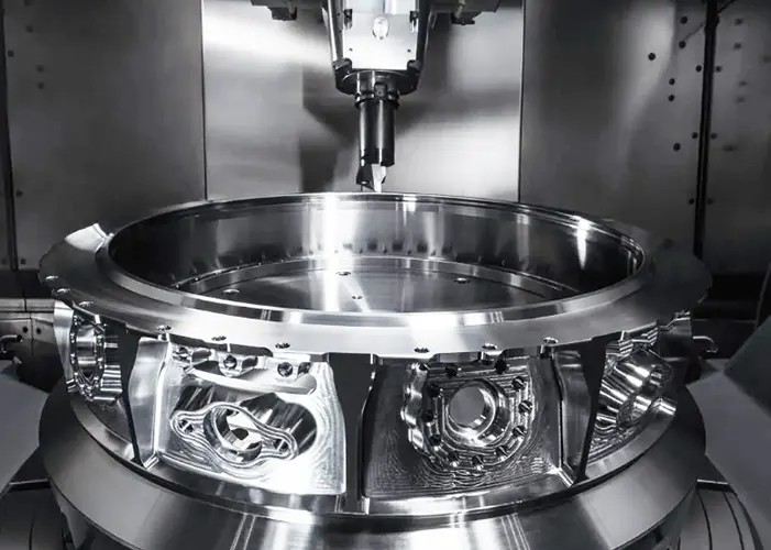
With the continuous development of the mechanical processing industry, CNC multi-axis machining technology has gained widespread application.
Characterized by high efficiency and stable processing, multi-axis machining technology is advancing toward integrated, high-precision, and multi-functional capabilities.
In practical multi-axis machining operations, automated programming presents considerable complexity. Modern CNC programming CAM software has developed mature machining strategies, extensively applied in product design and manufacturing.
Employing CAM to assist part design and machining enhances product design quality, shortens processing cycles, and improves economic efficiency.
This paper uses a complex part as an example, employing MasterCam software for part modeling, machining process design, and program creation. The post-processed program is then transferred to the machine tool for CNC machining.
Process Analysis
This study examines a cover component from a CNC multi-axis machining skills competition. The cover part, shown in Figure 1, has external dimensions of 198 mm × 155 mm × 20 mm and is machined from a square steel blank measuring 202 mm × 160 mm × 25 mm.
Due to multiple dimensional tolerance requirements and beveled surfaces on both sides, a four-axis machining center is selected for processing. Fixturing and positioning are achieved using a vise and bridge plate to ensure machining accuracy.
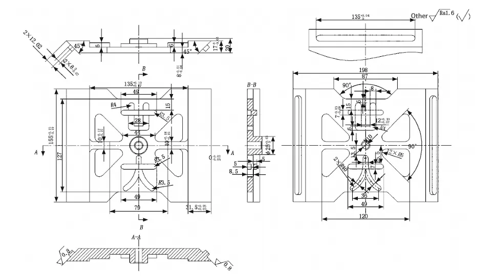
The machining process was planned according to the part drawing specifications. Front-side features were machined first, followed by reverse-side features, chamfers, and bosses. A VDM850E four-axis CNC milling machine was employed.
> Process Plan
The specific process sequence is as follows:
- Front-side Machining:
(1) Use a Φ63 face milling cutter with “bidirectional” cutting to machine the flat surface.
(2) Rough the surface using a 12mm end mill with a “dynamic milling” approach.
(3) Drill the central hole using an 8.5mm drill bit with a “peck drilling” method.
(4) Finish the bottom surface using a 20mm end mill with a “zone milling” feed pattern.
(5) Use a Ф10 end mill with a “contour milling” feed pattern for side wall machining.
(6) Use a Ф10 chamfering tool for chamfering.
- Part reverse side machining:
(1) Use a Ф63 face mill with a “bidirectional” cutting method for machining flat surfaces.
(2) Use a Ф6 end mill with an “oblique plunge” milling method for slot machining. (3) Use a Ф12 end mill with a “dynamic milling” method for rough machining.
(4) Use a 10 end mill for finish machining of the beveled surface.
(5) Use a 10 chamfering tool for chamfering.
Programming Simulation and Machining Design
> Part Modeling
MasterCam software was employed for this model design. Its effective integration with CNC machining yields excellent results. This software is widely used in CNC turning, CNC milling, and mold engineering projects, significantly advancing technological development in related fields.
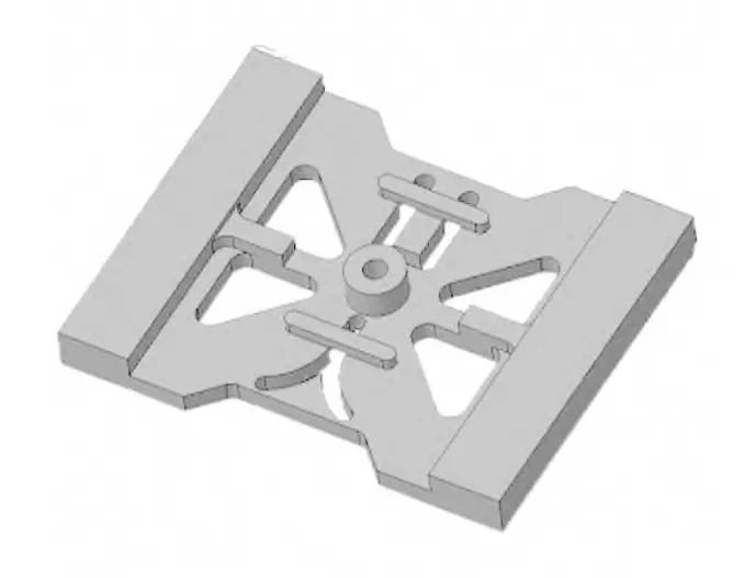
The upper cover part model was created using MasterCam’s modeling commands, including wireframe drawing and solid extrusion.
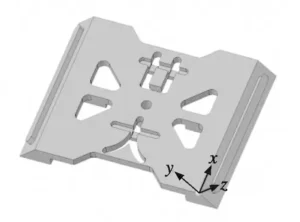
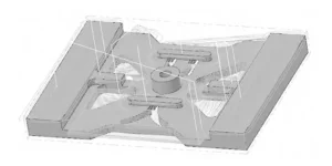
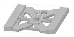
Since the front and back surfaces with tapered edges require separate machining, two solid models were created for convenient processing: one without tapered edges (Figure 2) and another with tapered edges (Figure 3).
> Programming Design for Front-Side Machining
Rough Machining
This part requires machining on both the front and back sides, starting with rough machining of the front side. Rough machining is time-consuming and challenging, so setting appropriate spindle speed and feed rates ensures efficient completion.
(1) Face Milling. The part blank is set as an enclosed cube. Face milling is performed using a 63mm diameter face milling cutter. The cutting method employs bidirectional machining with a stepover set at 90% of the tool diameter. Climb milling is used with a spindle speed of 4,000 rpm and a feed rate of 1,000 mm/min.
(2) Roughing of Side Walls. Dynamic milling is employed for roughing. A 12mm end mill is selected. During roughing with this tool, the spindle speed is 5000 rpm, the feed rate is 2000 mm/min, the cutting direction is set to down-milling, the side wall allowance is 0.5mm, and the stepover is set to 2mm.
(3) Bottom Surface Roughing. Employing the same 12mm end mill for dynamic milling, the cutting direction is set to up-milling. Both side wall and bottom surface allowances are 0.5mm, with a step size of 2mm.
The roughing toolpath is illustrated in Figure 4.
Hole Machining
Perform hole machining using an 8.5mm drill bit with G83 peck drilling cycle. For threaded sections of the part, employ manual tapping.
Finishing
(1) Bottom Surface Finishing.
You finish the bottom surface using a zone milling toolpath with a 20mm face milling cutter. You set the feed rate to 1000 mm/min and the spindle speed to 4000 r/min, using climb milling with a 0.5 mm wall edge allowance.
(2) Side Wall Finishing. Employ contour milling for side wall machining. Since different tools are used for the bottom surface and side walls, set the bottom surface allowance to 0.02mm during side wall finishing.
Due to multiple dimensional tolerances on the part, when finishing the side walls, first machine the right end of the part. Adjust the tool offset to ensure measured dimensions fall within tolerance limits before machining the remaining side walls.
The finishing toolpath is shown in Figure 5.
Chamfering
Profile milling is used to chamfer all edges with a chamfering tool.
> Programming Design for Back Side Machining
(1) Face Milling.
The reverse side face milling uses a Ф63mm face milling cutter with parameters identical to the front face milling.
(2) Slot Machining.
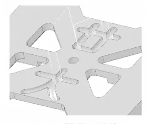
For narrow slots, a Φ6mm end mill is used for contour milling. The milling method employs an oblique approach with a depth set to 0.5mm. The toolpath contour is shown in Figure 6.
(3) Bevel Machining.
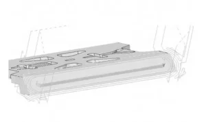
For bevel surfaces, you perform rough machining dynamically using a 12mm end mill, as shown in the toolpath profile in Figure 7. Then, you use a 10mm end mill to finish the face and side walls.
(4) Chamfering
You perform chamfering on all edges using a chamfering cutter for contour milling.
Machine Tool Design
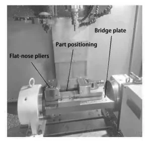
Due to the presence of beveled bosses on both sides of the workpiece, this design employs a bridge plate combined with a vise for machining.To minimize vise clamping operations, you mount the vise on the bridge plate during part processing. Figure 8 shows the fixture installation position.
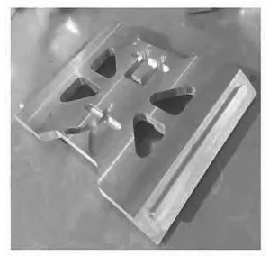
When machining features on both sides, the bridge plate rotation angle is set to 0. For the inclined boss, align the bridge plate rotation center, offset the workpiece coordinate system, and then proceed with machining. Figure 9 shows the phsical machined part.
Conclusion
This paper analyzes the machining process of a cover part from a CNC multi-axis machining competition using MasterCam software. By optimizing parameter settings and using an auxiliary bridge plate, the team successfully machined complex parts with inclined features.
FAQ
How does Mastercam support multi-axis machining?
Mastercam provides comprehensive CAM programming tools that simplify complex multi-axis operations. It allows users to model parts, design machining processes, simulate toolpaths, and generate accurate G-code for CNC execution.
What are the key advantages of using CAM software like Mastercam?
CAM software improves design accuracy, shortens machining cycles, reduces programming errors, and optimizes toolpath efficiency. It also enhances economic performance by minimizing waste and rework.
What are the main steps in CNC multi-axis machining using Mastercam?
The process typically includes:
Importing or modeling the part in Mastercam.
Designing machining sequences (face milling, roughing, drilling, contouring, etc.).
Simulating toolpaths for error detection.
Post-processing the program and transferring it to the CNC machine for execution.
What tools are commonly used in multi-axis machining?
Common tools include face mills, end mills, drills, and chamfer cutters. Tool selection depends on the operation type—such as roughing, contouring, slotting, or bevel machining—to achieve the desired precision and finish.
How is fixturing handled in multi-axis machining?
Fixturing ensures accurate part positioning and stability. In the study example, a vise combined with a bridge plate was used to maintain precision during both front and back machining, minimizing repositioning time and errors.
What machining strategies were applied in this Mastercam project?
The project applied a mix of bidirectional milling, dynamic milling, peck drilling, and zone milling strategies. These techniques optimized tool engagement, improved chip evacuation, and reduced machining time.
How do you ensure machining accuracy for complex parts?
Accuracy is ensured by optimizing parameters like spindle speed, feed rate, and cutting depth. Simulation in Mastercam allows engineers to verify toolpaths and adjust offsets before actual machining, reducing tolerance errors.
What were the results of this machining project?
The optimized machining plan using Mastercam and a four-axis milling machine successfully produced the cover part with high dimensional accuracy, smooth surface finish, and efficient cycle time — validating the effectiveness of the proposed process.
Why use a four-axis machine for this part?
The cover component contained multiple beveled surfaces and tolerance-sensitive features that required simultaneous multi-directional cutting. A four-axis CNC machine provided the necessary flexibility and precision for these operations.
Can Mastercam be used for both modeling and programming?
Yes. Mastercam supports both 3D modeling and toolpath programming, enabling engineers to complete the entire workflow — from part design to CNC machining — within one integrated platform.
How can using Mastercam improve production efficiency?
By automating toolpath generation, simulating machining steps, and minimizing trial errors, Mastercam helps manufacturers shorten production cycles, improve part quality, and enhance overall productivity.

