With the continuous development of the machinery manufacturing industry, conventional 3-axis milling machines have become widely used across industrial enterprises due to their low cost.
However, their limited machining capabilities can no longer meet the demands for processing complex and diverse parts, leaving these machines facing significant challenges of underutilization and waste.
Upgrading existing 3-axis milling machines with CNC capabilities enables multifunctionality, serving as an effective pathway for low-cost, high-efficiency equipment modernization.
This holds substantial practical significance for most enterprises.
This paper analyzes the automation upgrade of milling machines using the implementation of helical groove milling as an example.
This approach not only reduces costs for companies but also expands an enterprise’s overall manufacturing capabilities.
Issues in Milling Machine Processing Technology
From the perspective of conventional 3-axis CNC milling machine applications in enterprise production, they cannot perform helical groove milling.
Directly employing a four-axis milling machine with a rotary axis for helical slot milling incurs high costs.
To meet helical slot processing demands while reducing investment, enterprises typically automate milling machines by adding fully automatic helical indexing work platforms, enabling three-axis CNC milling machines to perform automated helical slot machining.
In practice, helical groove machining primarily involves gearing the universal indexing head to the milling machine’s longitudinal worktable.
By combining the horizontal movement of the worktable with the rotational drive of the indexing head, efficient and effective helical groove machining is achieved.
However, actual production faces drawbacks such as cumbersome gearing stroke calculations and significant machining errors.
Complex Gear Engagement Travel Calculation
Traditional gear engagement requires calculating both helical and horizontal feed travels, with significant variations across different component machining processes.
Combined with the time needed for gear installation and adjustment, this results in low overall helical groove machining efficiency and places high demands on milling operators.
Significant Machining Errors
Clearances between threaded wheels and milling machine lead screws readily accumulate excessive errors, compromising dimensional accuracy of machined components.
Simultaneously, threaded wheel connection methods disrupt smooth feed operations.
Particularly with small leads, substantial feed resistance causes vibration marks on component surfaces, degrading machining precision.
Principles of CNC Milling Operations
During CNC milling, the first step is to define the workpiece processing flow and relevant parameters. Based on these parameters, the CNC system is programmed to generate execution instructions.
These instructions drive the motor to move the cutting tool along a predetermined trajectory at specified speeds, completing the workpiece machining process.
The specific steps are as follows: When formulating the machining process flow and tool trajectory, comprehensively consider the workpiece’s dimensions, shape, and material properties to optimize machining parameters and auxiliary operations.
Program the code and input it into the CNC device. Start the lathe to send pulses to the servo system according to the predetermined program.
Modify, inspect, and test the servo system driving the lathe to ensure it can perform turning operations along the predetermined trajectory.
Optimization Approach
Integrating industry processing experience with advanced information technology applications, the optimization strategy for helical slot milling on milling machines can be analyzed from the following four aspects.
(1) Milling CNC Systems.
Small and medium-sized enterprises rarely possess high-end milling machines. From the perspective of business development and cost reduction, their milling CNC systems must offer high performance at low cost.
Currently, standard milling CNC systems include: – Open-loop systems driven by stepper motors – Closed-loop systems with optical grating measurement – AC/DC servo motor-driven systems – Asynchronous motor-driven systems – DC motor-driven systems – Semi-closed-loop systems with encoder feedback. Selection should balance cost and precision requirements.
(2) System Device Structure.
An upgraded CNC milling machine must meet requirements for high strength and rigidity, as well as low friction coefficients.
Taking the two primary mechanisms—linear motion and rotary motion—as examples:
– Linear motion can utilize ball screws and linear guides for transmission.
– Rotary motion can employ bearing transmission to ensure smooth and stable feed, achieving fully automatic helical motion under program-controlled two-axis linkage.
(3) Equipment Feed Mechanism.
Optimizing the feed mechanism requires adherence to three key principles:
First, ensure modified components possess high strength, precision, and adequate wear resistance;
Second, guarantee reliable component coordination after structural improvements to reduce failure rates;
Third, prioritize cost-effectiveness.
(4) Software Programming.
Reasonable software programming enhances the precision and efficiency of automated operations.
Therefore, after optimizing the device structure, feed mechanism, and CNC system for the automated retrofit of helical groove milling on milling machines, software programming must also be performed.
Automated Retrofit Plan
CNC System Processing
When selecting a CNC system, enterprises should comprehensively evaluate actual operating conditions, prioritizing solutions that meet most milling machine processing requirements.
For cost-effective applications, enterprises may opt for open-loop systems driven by stepper motors.
These systems are favored for their simple structure, lower cost, and ease of retrofitting.
From a system composition perspective, key components include stepper motors, power stepper motors, and electrohydraulic pulse motors.
In practical applications, this system does not require real-time transmission of position or speed data.
Instead, it relies on the system’s displacement accuracy to determine the angular displacement precision of the stepper motor.
For scenarios with relatively high machining accuracy requirements, this system remains a viable solution.
System Structure Design
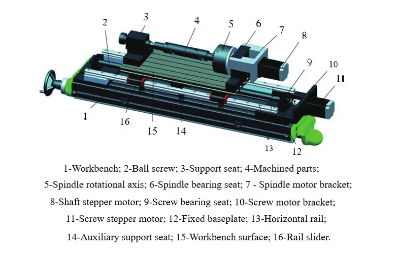
Integrating the aforementioned optimization principles, the automated retrofit of this helical groove milling system can focus on optimizing both the horizontal motion and helical motion mechanisms.
Programmed shaft coupling control achieves automated helical milling motion. The specific optimization design is outlined below.
Program-controlled structures are added to the linear motion mechanism to implement fully automated helical motion.
Components include the lead screw bearing housing, linear guide, guide slider, worktable surface, lead screw drive stepper motor, and auxiliary supports.
Program-controlled devices are integrated into the rotational motion mechanism to enable fully automated helical movement of all components.
These components comprise the rotary shaft bearing housing, support tailstock, and corresponding parts.
During system operation, first secure the device to the milling machine worktable.
Then connect the lead screw stepper motor and rotary shaft stepper motor to their respective interfaces.
Edit the corresponding program based on the lead of the component’s rotary groove.
Subsequently, perform tool setting and execute the automatic helical groove machining process to complete the automated production of helical grooves on the component.
The optimized milling machine structure is shown in Figure 1.

Feed Mechanism Enhancements
Within the feeding system, the drill rod’s rotational motion is primarily achieved through the secure grip of a pneumatic chuck.
Meanwhile, the cutting tool’s rotation is provided by a BT40-specification power spindle, capable of reaching a maximum rotational speed of 3,000 r/min.
Appropriate rotational and feed speeds are adjusted according to varying pitch requirements to ensure smooth machine operation throughout the entire machining process.
Tool loading and unloading are performed using a pull-rod clamping mechanism.
Selection is based on practical applications involving sliding rails and sliding screws.
When automating sliding rail systems, ensure high precision and strength to guarantee wear resistance, prevent deformation from affecting machined part accuracy, and implement routine rail protection and lubrication (e.g., bonding PTFE tape).
For sliding screws and backlash-free screws, experience indicates that the screw primarily governs transmission chain precision. Screws influence both machined part accuracy and drive torque.
Therefore, standard milling machines may utilize sliding screws exceeding Grade 6, which offer lower cost and precision, suitable for general-accuracy products.
For products requiring higher machining precision, backlash-free screws should be selected. These offer advantages such as high precision, low wear, and reduced tool breakage.
Software Programming and Application
Currently, with the diversification of groove machining methods and types, helical groove machining—due to its unique difficulty and process requirements—urgently necessitates the use of information technology to achieve milling process automation.
The fundamental approach involves using Mastercam software to construct a digital model of the helical groove.
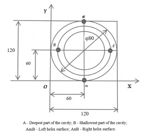
By referencing the principles governing helical surface formation, the lowest and highest points of the helical groove cavity are determined, and corresponding programs are generated.
Subsequently, the coordinate values and lead of the tool center path are calculated.
Through software programming, CNC milling equipment achieves automated machining.
Theoretically, this approach offers high efficiency, precision, and quality. A schematic view of the helical groove plane is shown in Figure 2.

» Construction of Helical Groove Digital Model
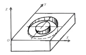
Mastercam software can be employed to construct the digital model for helical groove machining, as depicted in Figure 3. The model construction must be grounded in practical considerations to ensure reliability for subsequent automated analysis.

» Automated Program Development and Application
After utilizing Mastercam software, users can export the corresponding programs.
Engineers then appropriately modify these programs based on calculated lead information and tool center path data, including operations such as “Z-axis feed” and “rapid traverse to point B.”
Subsequently, the automated program is initiated, prompting the CNC milling machine to commence cutting operations for the digital machining of the workpiece’s helical groove.
Application Results
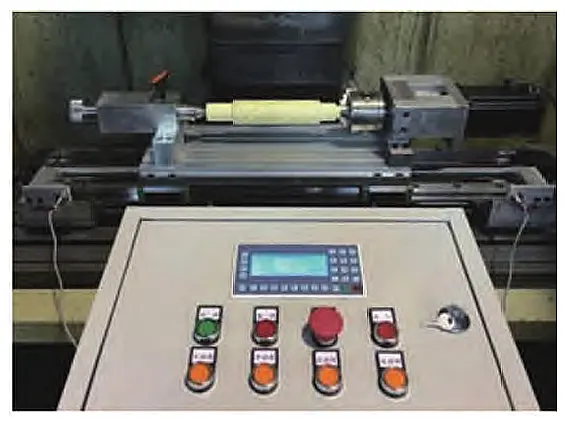
To test the practicality of this device, the team developed a prototype based on the design drawings and subjected it to milling operations.
Figure 4 shows the prototype, which was appropriately scaled down compared to the actual milling machine worktable setup.
Actual testing confirmed that all functions of the prototype performed effectively.
Compared to milling machines, this device enables high-precision helical groove machining and demonstrates strong adaptability for three-axis milling machine tables.
It effectively addresses issues such as high manufacturing costs for high-end equipment and low machining accuracy in traditional three-axis gear-driven solutions for helical grooves.
Furthermore, its relatively simple structural design offers broad market application prospects.

After repeated experiments, the team established the final machining parameters: a helical rotation speed of 1,700 r/min and a feed rate of 8,000 m/min.
At the customer’s worksite, operators used brand-new cutting tools for continuous cutting operations until slight surface roughness appeared on the workpiece.
The machines successfully processed 730 products over a 4-hour operation without experiencing any failures throughout the entire machining process.
Conclusion
The automation retrofit of conventional three-axis milling machines for helical groove machining provides enterprises with a practical, low-cost, and high-efficiency modernization pathway.
By integrating optimized CNC systems, enhanced feed mechanisms, and advanced software programming, enterprises can overcome the limitations of traditional gear-driven methods.
The prototype testing demonstrated stable performance, high machining precision, and strong adaptability to real-world production environments.
Continuous cutting trials confirmed the device’s reliability, with 730 products successfully processed in four hours without machine failures.
This approach not only reduces equipment investment and operating costs but also expands the manufacturing capabilities of enterprises.
With its simple structural design, robust performance, and proven practicality, the proposed solution offers broad application prospects for industries seeking to improve machining efficiency and competitiveness.
FAQ
Why are conventional 3-axis milling machines no longer sufficient for modern manufacturing?
Conventional 3-axis milling machines are cost-effective but lack the capability to handle complex and diverse part geometries. As industries demand higher precision and multifunctionality, these machines face challenges of underutilization and waste.
How can upgrading 3-axis milling machines with CNC capabilities improve performance?
Upgrading 3-axis milling machines with CNC systems transforms them into multifunctional equipment, enabling automation, precision, and cost efficiency. This modernization allows enterprises to meet advanced machining requirements without investing in expensive high-end machines.
What is helical groove milling, and why is it important?
Helical groove milling is a machining process that creates spiral-shaped grooves on components. It is widely used in industries requiring high-precision parts. Automating this process on 3-axis machines significantly expands manufacturing capabilities while lowering costs.
Why is retrofitting 3-axis machines more cost-effective than purchasing 4-axis or 5-axis machines?
Four-axis and five-axis machines are costly investments. Retrofitting existing 3-axis machines with automated helical indexing work platforms enables similar functionality at a fraction of the cost, making it a practical solution for small and medium-sized enterprises.
What challenges exist in traditional gear-driven helical groove machining?
Traditional methods involve complex gear engagement calculations and lengthy setup times. They often lead to machining errors due to screw clearances, vibration marks, and resistance during small-lead cutting, reducing overall efficiency and accuracy.
What role does CNC programming software like Mastercam play in automation?
Mastercam software is essential for constructing digital models of helical grooves. It helps calculate tool path coordinates, generate machining programs, and optimize tool movements. This software-driven approach improves precision, efficiency, and repeatability.
How does the optimized feed mechanism enhance automated milling performance?
An improved feed mechanism with ball screws, linear guides, backlash-free screws, and pneumatic chucks ensures smooth motion, reduced wear, and consistent machining accuracy. These upgrades also minimize tool breakage and improve long-term reliability.
What are the proven results of automating helical groove milling on 3-axis machines?
Prototype testing confirmed stable and precise performance. Continuous operations processed 730 products in just four hours without machine failures, proving both efficiency and reliability in real production environments.
What are the economic benefits of CNC retrofitting for enterprises?
CNC retrofitting reduces capital investment, lowers production costs, and extends the service life of existing machines. At the same time, it boosts productivity and enhances competitiveness in the manufacturing market.
Which industries can benefit from automated helical groove milling?
Industries such as aerospace, automotive, energy, and precision engineering benefit greatly. Automated helical groove milling supports high-precision, complex part production, offering a scalable and cost-effective solution for enterprises of all sizes.

